All published articles of this journal are available on ScienceDirect.

Characteristics of the Tooth in the Initial Movement: The Influence of the Restraint Site to the Periodontal Ligament and the Alveolar Bone
Authors Info & Affiliations
Abstract
It is critical to clarify orthodontic load transfer mechanism from tooth to alveolar bone, and to determine the influence of applied orthodontic force on tooth behaviour. In this study, two dimensional (2-D) finite element (FE) models were constructed to simulate to mechanical behaviour observed during the initial movement of periodontal ligament (PDL) deformation, and to evaluate the effects of the presence of PDL and various restraint sites on tooth behaviour.
A 2-D solid FE model of the tooth-PDL-alveolar bone system was constructed and investigated into stress distribution pattern and displacement. The first analysis was carried out with combinations of FE model with and without PDL. The second analysis was compared with three different sites restraint of alveolar bone.
By incorporating PDL in FE models, excessively large stress values and deformation generated in a tooth and alveolar bone were relieved. Since restraint conditions did not affect a tooth and PDL, but had an effect on alveolar bone, orthodontic force necessary for tooth displacement was transmitted correctly. The results of this study revealed that inclusion of PDL in FE models is indispensable to transmit orthodontic force appropriately when investigating tooth behaviour for orthodontic treatment. Restrained sites affected stress distribution in alveolar bone.
INTRODUCTION
In orthodontic treatment, an esthetics are restored by moving an irregular tooth to right position by applying orthodontic forces to bracket, wire, and elastic band. To displacement of a tooth, large orthodontic force exceeding friction force generated in a bracket and a wire must be applied [1]. The application of large orthodontic force impedes the blood supply of periodontal ligament (PDL), causing ischemia [2-4]. Ischemic situation affects metabolism of oxygen, leading to the initiation of periodontium remodelling processes. Due to strict restrictions on in vivo experiments, orthodontic bone remodelling processes have been mainly analysed from a biomechanical point of view using models simulating what actually occurs in the oral environment. Several studies such as dial gauge method, straight gauge method, distribution method and vibration method have been reported regarding orthodontic tooth movement [5, 6]. Orthodontic remodelling processes are divided into two stages, i.e. initial tooth movement period when PLD is mainly deformed, and second tooth movement period when a whole periodontium included alveolar bone are deformed [7]. Due to the difficulty of making a model of periodontium included PDL, the results from a conventional study using a model are thought to be inaccurate and differ from what actually occurs in a living body. With the development of computer technology, Finite Element (FE) method has been widely used in dentistry for the evaluation of biomechanical situations [8-13]. It is critical to clarify orthodontic load transfer mechanism from a tooth through PDL to alveolar bone, and to reveal the influence of applied orthodontic force on tooth behaviour, which might be precious guidelines for orthodontic treatment.
The aims of this study were to compare and evaluate the effect of the presence of PDL and various restraint sites, during initial tooth movement of PDL deformation, on tooth behaviour and stress distribution patterns, using FE analysis.
MATERIALS AND METHODOLOGY
Tooth behaviour with or without PDL under various restraint conditions was observed using different two dimensional (2D) FE models of mandibular central incisor.
1. FE Model Preparation
A 2D FE model of the tooth-PDL-alveolar bone system (ellipse-shaped) representing mandibular central incisor was constructed (Fig. 1).
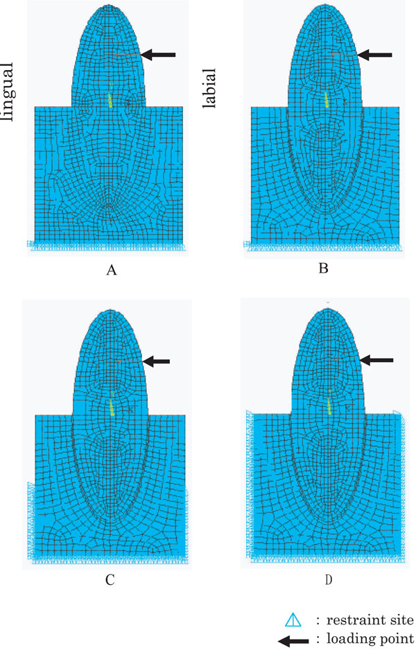
2-D FE models of mandibular central incisors under various conditions.
A: Model A, without PDL and base restrained, B: Model B, with PDL and base restrained, C: Model C with PDL and base + side 1/2 restrained, D: Model D with PDL and a whole restrained.
A 2D model was to be in the middle of both buccolingual and mesiodistal diameters and along the long axis of a crown. A 2D model used in this study assumed to have the following dimensions, crown and root lengths 12.0mm each, labiolingual diameter of a crown 8.0mm and PDL 0.2mm. The distance between cervical area and base of mandible was assumed to be 16.0mm and labiolingual diameter of alveolar bone 10.0mm [14]. Two different 2D FE models were prepared for this study, i.e. the tooth- alveolar bone continuum (abbreviated as model without PDL) and the tooth-PDL-alveolar bone continuum (model with PDL). As restraint conditions, alveolar bone was restrained in three different sites, i.e. the base of alveolar bone (base), the base of alveolar bone and the lower one half of labiolingual sides (base+side1/2) and the base of alveolar bone and labiolingual sides (a whole side). Thus, four different kinds of FE models were created, i.e. model A (without PDL and base restrained), model B (with PDL and base restrained), model C (with PDL and base+side1/2 restrained) and model D (with PDL and a whole restrained). Analyses were carried out with combinations of analysis 1 (model A and model B), and analysis 2 (model B, model C and model D).
2. Boundary Conditions
Quadrilateral elements with 8 nodes having middle nodes, consisted of 1,146 elements with 3,575 nodes, were created for this plane analysis. Movements in labiolingual direction on the base of alveolar bone were restrained, which defined as restraint conditions. A single, concentrated load of 1.0N [15] was applied from labial to lingual directions at the central part of a crown, where a bracket is to be seated. Analysis was presumed to be linear static. The corresponding material properties such as Young’s modulus and Poison’s ratio were listed in Table 1.
Material Properties Used in the Present FEM Simulations
| Youngs Modulus (MPa) | Poissons Ration | |
|---|---|---|
| Tooth Substatance | 8.0 x 10⁴ | 0.30 |
| Periodontal Ligament | 1.8 x 10⁻¹ | 0.49 |
| Alveolar Bone | 7.8 x 10³ | 0.30 |
FE model construction and FE analysis were performed on PC workstation (Precision Work Station 530, Dell Computer) using commercially available FE analysis software (ANSYS 9.0 ANSYS Inc. Houston, USA). The width of contour between analyses 1 and 2 was changed so as to differentiate the difference of stress values between them. The stress analysis was performed using equivalent (Von Mises) stress values which summarise the effect of six stress components in a unique value. In the mathematical formula, considering the three principal stress components (σ1, σ2 and σ3), the von Mises stress value was defined as follows:
RESULTS
1. Analysis 1
The behaviour of mandibular central incisor with or without PDL and base restraint
1.1. Equivalent Stress Distribution Pattern
Figs. (2a and 3a) show equivalent stress distribution pattern observed in model A and model B, respectively. In model A, 0.4~0.8MPa stresses were found in cervical area and 0.1~0.4MPa stresses in alveolar process. Relatively small stresses of 0.1~0.5 MPa were observed in root apex, showing integrated stress distribution pattern with alveolar bone. Stress distribution pattern demonstrated almost line symmetry against major axis of the tooth.
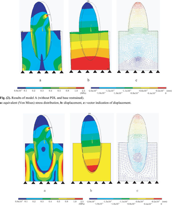
Results of model A (without PDL and base restrained).
a: equivalent (Von Mises) stress distribution, b: displacement, c: vector indication of displacement.
Results of model B (with PDL and base restrained).
a: equivalent (Von Mises) stress distribution, b: displacement, c: vector indication of displacement.
In model B, 0.4~0.8MPa stresses were found in cervical area, 0.1~0.2 MPa stresses in alveolar process, and 0.1~0.2MPa stresses in PDL around cervical area. At the corresponding root apex, different magnitude of stresses were observed in PDL (0.1~0.3 MPa) and in alveolar bone (0.5~2.5 MPa). Like model A, stress distribution pattern of model B demonstrated almost line symmetry against major axis of the tooth.
1.2. Displacement Distribution Pattern
An overall displacement of model A (Fig. 2b) was smaller than that of model B (Fig. 3b), and model A was inclined to negative direction of X axis pivoting on the centre of model base. As to displacement of alveolar bone in model A, -1.1x1.0-3~0.9x10⁻³mm displacement were found at alveolar process, and -0.2x1.0-3~0.0mm displacement were found near alveolar base. With respect to displacement of PDL in model B, -0.9 x1.0-3~-0.2 x1.0-3mm displacement were found from cervical area to root apex.
1.3. Displacement Vector
In model A (Fig. 2c), displacement vectors of both alveolar bone and crown-tooth root drew the same circular arc centring on the model base. Tooth with PDL were deformed obliquely as one body. In model B (Fig. 3c), on the other hand, displacement vector of alveolar bone surrounded the PDL, whereas displacement vector of crown-tooth root drew circle centring on the middle of the root, making a turn due to viscoelastic characteristics of PDL.
2. Analysis 2
The behaviour of mandibular central incisor with PDL and various restraint sites.
2.1. Equivalent Stress Distribution Pattern
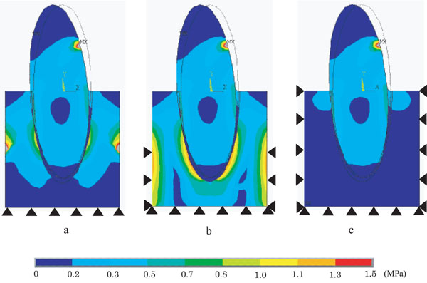
Fig. (4) demonstrates equivalent stress distribution patterns under various restraint conditions, such as model B (Fig. 4a), model C (Fig. 4b) and model D (Fig. 4c). No significant differences in stress distribution between the models were found in the cervical area of the tooth and PDL.
Difference of equivalent (Von Mises) stress distribution on PDL models with various restraint conditions.
a: Model B (base restrained), b: Model C (base + side 1/2restrained), c: Model D (a whole restrained).
In alveolar bone of model B and model C, relatively high stresses of 0.3~1.0MPa were observed at both sides of alveolar bone and around the root. Particularly model C showed significantly higher stress values compared with model B, e.g. 0.5~1.3MPa stresses were found around the area of the root.
In alveolar bone of model D, 0.3MPa stresses generated in cervical margin of alveolar process were gradually decreased toward alveolar base.
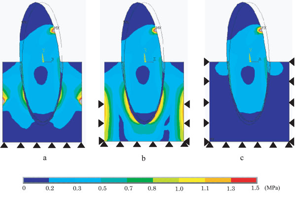
2.2. Displacement Distribution Pattern
Fig. (5) shows displacement distribution pattern under various restraint conditions, such as model B (Fig. 5a), model C (Fig. 5b), and model D (Fig. 5c). No significant differences in displacement were found in tooth and PDL under any restraint conditions. In alveolar bone, however, displacement decreased toward alveolar base in accordance with expanding restraint area. Displacement distribution pattern under three different restraint conditions showed almost symmetric line against longitudinal axis of the tooth. Tooth and PDL were inclined from labial side to lingual side at the middle of the root as a border line.
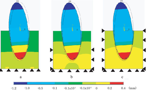
Difference of displacement on PDL models with various restraint conditions.
a: Model B (base restrained), b: Model C (base + side 1/2 restrained), c: Model D (a whole restrained).
2.3. Displacement Vector
Fig. (6) shows displacement vector of model B (Fig. 6a), model C (Fig. 6b), and model D (Fig. 6c), respectively. Under any restraint conditions, displacement vector of tooth-PDL continuum drew circle centring on the middle of roots. In alveolar bone, model B showed M-shaped orientation of displacement vector surrounding PDL in alveolar bone. Model C drew circles centring on the root apex and on 1/2 side of restraint sites, while model D drew circular arcs centring on the middle of the root.
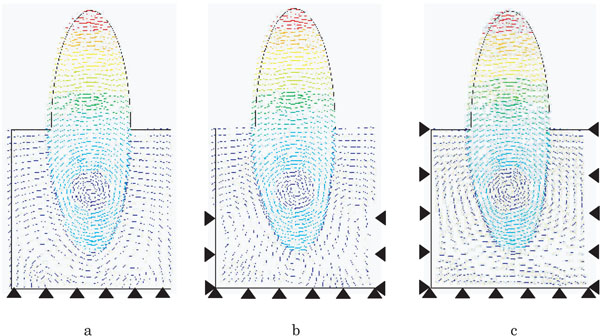
Difference of vector indication of displacement on PDL models with various restraint conditions.
a: Model B (base restrained), b: Model C (base + side 1/2 restrained), c: Model D (a whole restrained).
DISCUSSION
1. FE Method and Modelling
Although actual measurements and clinical trials have been carried out to investigate the influence of the presence of PDL on tooth and alveolar bone behaviour, it is difficult to compare the test results [16-20], because tooth differs from each other in terms of geometry, morphology and dimensions. The FE method has become one of the most frequently used analysing methods when evaluating the dental related issues. Unlike with many other FE applications, certain assumptions need to be made when dealing with complicated set of teeth, bone or PDL. The FE method approach requires not only an agreement of dimensions and material properties of the experimental structures, but also precise calculation of the inner stresses. This makes the construction of FE models difficult. FE study was chosen for this study, because FE models remained same without being affected by the restraint sites. Furthermore, FE analysis enabled to evaluate the influence of different restraint sites [21-24].
In this study, a 2D FE model was chosen primarily because it enabled the analysis of stress, displacement and vector direction distribution, with different boundary conditions in the same FE model with identical material properties. If other variables would have been added, the simulated situation would have not identified the results of the stress distribution. In the previous study, 2D FE analysing method was used to evaluate the stress of the bone and implant [25-27]. Evaluation of the stress distribution using a 2D FE model has showed as a very effective analyzing method in the dental science. The results of this study helped the selection of the boundary condition. However, within the limitation of this 2D FE model, the mechanical behaviour of the PDL and the remodelled bone remained naturally unknown, which should be taken into consideration upon the accurate clinical condition.
2. The Effect of the Presence of PDL on Tooth Behaviour
PDL plays an important role in the orthodontic tooth movement. A 2-D FE analysis was performed to clarify the influence of the presence of PDL on tooth behaviour [1]. No significant differences in equivalent stress induced in cervical area of the tooth were found between model A and model B. Model A, however, exhibited two times as high as stress values at cervical margin of alveolar process compared with model B. In model B, relatively high stress values were observed within alveolar bone around the root. This may be explained by the fact that PDL has the capacity to absorb stress and to transmit much reduced stress to alveolar bone.
Significant differences in displacement were found between model A (Fig. 2b) and model B (Fig. 3b). Model A demonstrated relatively small displacement compared with model B, and also exhibited deformed displacement distribution pattern around cervical area of alveolar bone. Model A was inclined to lingual direction pivoting on the centre of model base, whereas model B was inclined to lingual direction pivoting on the middle of the root as the centre of resistance, which might be influenced by lower Young’s modulus PDL possesses. Since the model A assumed to have a perfect adherence (tooth and PDL, as well as PDL and alveolar bone), model A was thought to exhibit the same mechanical behaviour as a cantilever bridge, acting the fixed point as fulcrum. In short, restrained model base functioned as the centre of displacement. A bit of free tooth displacement within alveolar bone was allowed by including viscoelastic interference material with lower Young’s modulus between the loading point and the fixed point [28, 29], thus enabling the centre of displacement to move from the fixed point to the middle of the root.
When simulating orthodontic tooth movement, it is essential to include PDL in FE models so that the stress distribution within tooth and alveolar bone are reduced, and orthodontic force necessary to move tooth are transmitted correctly. In addition, FE model with PDL made it possible to demonstrate the centre of resistance within a tooth root [29-34].
3. The Effect of Various Restraint Sites on Tooth Behaviour
In order to better simulate the tooth displacement of natural oral environment, the evaluation of the influence of various restraint sites included PDL on tooth behaviour is critical. The present study was therefore done under three different restraint conditions.
When the effect of various restraint sites on equivalent stress distribution pattern was investigated, significant differences were observed within the alveolar bone. In model D (Fig. 4c), due to the influence of side restrained, stress generated within alveolar bone had a tendency to exhibit smaller value as it should be. In model C (Fig. 4b), due to the influence of lower 1/2 alveolar bone restrained, applied force was not fully transmitted to areas around the root, as well as excessively high stress values were obtained at the specific sites of both sides of alveolar bone. In model B (Fig. 4a), applied force was fully transmitted within alveolar bone to areas around the root without being affected by base restraint. No significant differences in equivalent stress distribution pattern were found in tooth and PDL under any restraint conditions. In displacement, no significant differences were found between the models investigated, and all models were inclined from negative direction to positive direction (Fig. 5). Fig. (6) represents the result of displacement vector under three different restraint conditions, which revealed that all three models had the centre of resistance at the same position.
The results obtained so far revealed that various restraint sites did not significantly affect tooth and PDL, but had a significant effect on alveolar bone. Therefore it is advisable to choose a restraint site having no specific influence on stress distribution of alveolar bone, whenever evaluation of alveolar bone is crucial. The results of this study clarified that base restraint showed the best simulation of what actually occurs in oral environment.
4. Clinical Implications
The results of this study indicate that, during initial movement of PDL deformation, the presence of PDL enabled to alleviate excessive stress concentration generated in tooth and alveolar bone, to appropriately transmit orthodontic force necessary to move tooth. Additionally, the presence of PDL allowed the middle of the root to occur the centre of resistance for oblique inclination. Various restraint sites did not significantly affect tooth and PDL, but had a significant effect on alveolar bone, indicating that findings obtained in this study will be important guidelines to simulate orthodontic tooth movement.
For the orthodontist, clinicians must know the mechanical behaviour of tooth, PDL and bone under the orthodontic force to prevent the root resorption. Now these days, new method using the micro implant technique for anchorage of the orthodontic force is available. There are no PDL around the micro implant. This technique will make more complicate the mechanical behaviour of tooth movement, because tooth with PDL and micro implant (without PDL) are connected and pull each other. This manuscript will help the orthodontists to understand about this kind of mechanical behaviour.
CONCLUSION
In the present study, 2D FE models were constructed to simulate mechanical behaviour observed during the initial movement of PDL deformation, and evaluated the effects of the presence of PDL and various restraint sites on tooth behaviour, stress distribution pattern and displacement. Within the limitation of this in vitro study, the following conclusions were drawn:
- By incorporating PDL in FE models, excessively large stress values and deformation generated in a tooth and alveolar bone were relieved, and orthodontic force necessary for tooth displacement was transmitted correctly. Furthermore, the presence of PDL enabled to make the centre of resistance for oblique inclination at the middle of the root.
- Since various restraint conditions had a significant effect on alveolar bone, the least affected site of base restraint should be chosen when evaluation of alveolar bone is critical.