All published articles of this journal are available on ScienceDirect.

Negative Pressure Irrigation Dynamics between Two Needle Designs using Computational Fluid Dynamics
Authors Info & Affiliations
Abstract
Objective:
This study aimed to investigate the irrigation dynamics of the EndoVac and modified apical negative pressure (mANP) using Computational Fluid Dynamics (CFD) for application in endodontic irrigation.
Methodology:
A simulation of a prepared root canal (conical frustum) of 12 mm length with an apical diameter of 0.40 mm following Protaper F4 apical preparation was created using three-dimensional (3D) CAD software. 3D simulated aspiration needles (EndoVac, micropores needle) and (mANP, 30G flat open-ended needle) were also created. The irrigation dynamics were evaluated through transient CFD simulations. In addition, the irrigation dynamics of mANP were also assessed at three different needle depths of insertion.
Results:
The EndoVac and mANP streamlines pattern showed irrigants able to reach the apical end. Both needle designs demonstrated negative static apical pressure. The mANP using an open-ended needle design revealed a higher average WSS magnitude in all three different needle depths of insertion compared to the EndoVac.
Conclusion:
CFD analysis of the EndoVac and mANP revealed that different needle designs and needle depth insertion affect the irrigation dynamics pattern and magnitude in a simulated root canal. The open-ended needle design of mANP1 contributed to the higher WSS magnitude, discharge coefficient, and apical static pressure compared to the EndoVac.
1. INTRODUCTION
Chemo-mechanical preparation using the appropriate selection of instruments and irrigation techniques is necessary for a successful endodontic treatment. Irrigant should be able to reach the working length and remove the smear layer and microorganisms from the root canal [1]. A syringe and needle instrument is a common technique for irrigation with a positive pressure irrigation system. However, caution must be exercised to avoid extruding the irrigant beyond the apex [2]. Perez et al. proved that the placement of the needle at 1mm short of the working length revealed higher percentage levels of hard-tissue debris removal compared to at 5mm short of the working length [3], however, it was found that positive pressure with side-vented needle delivers solutions no more than 0–1.0 mm beyond the needle tip [4, 5]. This revealed that positive pressure irrigation is insufficient for reaching the apical third [4] due to the stagnation plane [6]. Hence, new irrigants and irrigating devices are developed to improve root canal disinfection in endodontic practice [4]. Apical negative pressure (EndoVac), sonic activation (EndoActivator), passive ultrasonic (PUI) and Er: YAG laser are examples of promising techniques that claim to improve the irrigant’s effectiveness, particularly at the apical third of canal [7, 8]
The EndoVac system uses a negative pressure approach in which irrigant delivered in the pulp chamber is sucked down the root canal through a unique thin needle design [9]. Apical negative pressure was found to be effective in overcoming the difficulty of delivering irrigation to the most apical areas of the root canal system [10] and reducing the risk of irrigant extrusion [11]. Apical negative pressure also appears to be capable of removing the vapour lock, resulting in increased irrigation flow and apical root canal debridement [12]. Several studies have reported an increased efficacy in smear layer elimination at the apical region following the use of negative-pressure irrigation systems [4, 7]. Many studies on the efficacy of the EndoVac system seem to suggest that this system is the ‘gold standard’ of apical negative pressure irrigation [1]. Although EndoVac seems to be a promising delivery system, there are chances of the holes in the microcannula contacting the root canal wall and becoming blocked [13]. EndoVac was also reported to produce the lowest wall shear stress, proportional to the flow rate that was generated [14, 15]. Wall shear stress determines the mechanical effect of irrigation as it influences the detachment of debris, smear layer and biofilms from the root canal wall [16].
In recent years, Computational Fluid Dynamics (CFD) studies have been applied with great potential to study the flow pattern of irrigants in the root canal system [9, 16]. CFD analysis highlighted that flow patterns of irrigants, apical pressure, velocity and wall shear stress differed depending on the mode of irrigation [14, 15]. It is important to note that most CFD study analyzed EndoVac with a micropores needle as the negative pressure irrigation technique. Thus, there is a need to investigate the flow pattern and magnitude of other needle designs and needle depth insertion used in negative pressure irrigation techniques using CFD. Therefore, the aim of this study was to investigate on the irrigation dynamics of the modified apical negative pressure (mANP) in terms of wall shear stress, streamlines and apical pressure using computational fluid dynamics. The data is compared with the Endovac system at a similar operating condition.
2. MATERIALS AND METHODS
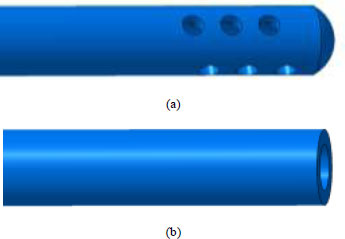
The root canal system was simulated as a geometrical frustum of a cone, with the apical terminus of the root canal simulated as an impermeable wall, with no simulation for the apical constriction and foramen [15]. The length of the root canal model was set at 12 mm, with a diameter of 0.40 mm at the apical point following Protaper F4 apical preparation (6% taper) [7]. 2 types of needles have been considered for the negative pressure approach, i.e., micropores EndoVac system (Sybron Endo, Orange, CA, USA) and 30G flat open-ended needle (a 30-G KerrHawe Irrigation Needle, KerrHawe SA, Bioggio, Switzerland) for modified apical negative pressure (mANP). Both the root canal and the needles were first modelled in CAD software (CATIA V5, Dassault Systèmes SE, France; (Fig. 1) for the depiction of EndoVac and mANP needles). The needle volume is then removed from the root canal volume through Boolean subtraction, which leaves the fluid domain only. To mesh the fluid domain, a blocked domain consisting of 128,000 hexahedral elements is first generated. The fluid domain is then imported to the blocked domain in an STL format and meshed using snappyHexMesh, a mesh generator utility in the OpenFOAM software (OpenCFD Ltd, Bracknell, United Kingdom).
A grid independence study was performed by monitoring the maximum and average wall shear stress, which significantly impacts the effectiveness of smear layer removal. The average wall shear stress was calculated by integrating the wall shear stress over the entire needle surface and dividing it with the needle surface area, i.e.
 |
where τ is wall shear stress and A s is needle surface area.
Furthermore, these parameters are known to be sensitive to the grid resolution, particularly in the near-wall region. Errors relative to the case with the highest resolution were defined as a monitor for each case. A demanding case of mANP placed 0.2 mm short of the working length was chosen for the test. The results are presented in Table 1. It shows the case with fine mesh achieved a 3.79% error at worst and is used hereafter. The mesh quality was monitored through the cells’ skewness and non-orthogonality. The EndoVac and mANP fluid domain consists of 1,498,634 and 1,523,214 hexahedra cells, respectively, with respective average non-orthogonality (maximum skewness) of 5.247 (3.174) and 5.04 (3.174).
| Mesh | Number of cells | The error of maximum wall shear stress (%) | The error of average wall shear stress (%) |
|---|---|---|---|
| Coarse | 1,011,747 | 3.25 | 7.24 |
| Fine | 1,523,214 | 2.32 | 3.79 |
| Finest | 2,890,263 | - | - |
The modes of negative pressure irrigation were divided into two groups. Group 1 consisted of a closed-ended with micropores needle by EndoVac (SybronEndo, Orange, CA, USA) and group 2 of 30G flat open-ended needle (a 30-G KerrHawe Irrigation Needle, KerrHawe SA, Bioggio, Switzerland). The tip of the micropores needle in group 1 is placed at the apex of the root canal following the manufacturer’s instructions. The needle consisted of 12 radially arranged holes, each of 0.10 mm in diameter, positioned between 0.2 and 0.7 mm from the tip of the needle [15]. For group 2, the 30-gauge open-ended needle was used with an external diameter of 0.320 mm and an internal diameter of 0.196 mm [16]. Group 2 needle was simulated at three different needle depth insertions (0.2mm, 0.5mm and 1.0mm short from the working length) to assess the flow pattern and magnitude. This is to evaluate the effect of needle depth insertion on the irrigant flow of the mANP needle and to compare with the previous study [17].
For both groups, the flow is driven by a pressure gradient of 88.326 kPa between the inlet and outlet surfaces (i.e. total inlet pressure of 101.325 kPa and static outlet pressure of 12.999 kPa), following [14]. The root canal is assumed to be filled with 3% NaOCl irrigant, which is modelled as a Newtonian fluid with kinematic viscosity ν = 9.6555×10⁻⁷ m2s-1. The governing equations (momentum and continuity) were solved by the finite volume solver pimpleFoam, which uses the PIMPLE algorithm from the OPenFOAM code library [18]. The solver was previously validated in [19]. To further validate the solver used in the present study, flows through an orifice plate were simulated and the discharge coefficients at various Reynolds numbers were compared with data from ISO 5167-2:2003. The results are depicted in Fig. (2). It was found that when compared to the data provided in the ISO 5167-2:2003, the present CFD simulations were found to accurately predict the discharge coefficients. At the highest Reynolds number of 50,000, the highest error of discharge coefficient was 3.70%. It is also worth noting that the trend of discharge coefficient with variation of Reynolds number is strikingly similar.
The transient analysis is carried out using the k-ω shear stress transport (SST) turbulence model, with time step size ranges between 3 × 10⁻⁶ s and 5 × 10⁻⁶ s. Comparison with the experimental in vitro model indicated that the k-ω SST turbulence model appeared to be the best fit for the problem under consideration [20]. An initial time step size of Δt = 10-4L/U∞ was imposed, and the values were automatically adjusted to match the specified maximum CFL. The turbulent intensity and the eddy viscosity ratio were set up at 5% and 10, respectively, following [14]. The flow is allowed to develop until start-up transients have attenuated.
3. RESULTS
The instantaneous wall shear stress distribution is presented in Fig. (3). The shear stress pattern on the canal wall was similar for mANP regardless of the needle distance. In general, the maximum wall shear stress occurs close to the tip of the open-ended needles. Whereas the EndoVac shear stress pattern showed localised maximum wall shear stress at a distant area from the tip even though the needle tip was placed at the apex.
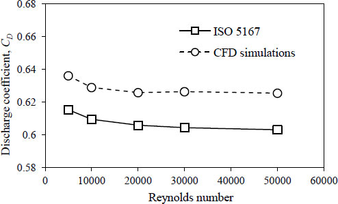
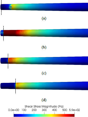
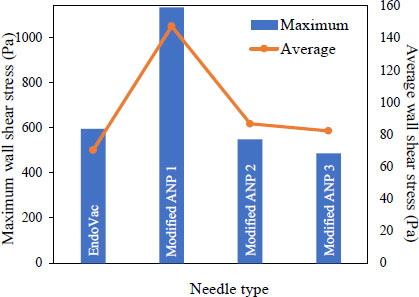
Fig. (4) shows the shear stress magnitude of the canal wall for different irrigation systems. mANP1 (0.2mm short from the working length) showed the highest maximum wall shear stress, followed by the EndoVac. Fig. (5a and b) revealed the EndoVac wall shear stress pattern. The EndoVac system, however, produces a different pattern of shear stress distribution on the canal wall than the open-ended needle. The flow developed a local maximum of wall shear stress in the vicinity of the pair of micropores furthest away from the apical. Both the EndoVac and mANP provide a good irrigant replacement as the streamlines are able to reach the apex, as shown in Fig. (6), since most of the debris or smear layer is accumulated at the apical third of the root canal. However, according to Fig. (7), the EndoVac showed less irrigant replacement compared to the mANP. The limitation of EndoVac was, most of the irrigant was aspirated through the furthest inlet away from the tip, thus less irrigant replacement at the apical tip compared to the mANP. Table 2 summarizes the magnitude value of irrigant flow rate, wall shear stress, discharge coefficient and apical static pressure.
| Needle | Flow Rate, ml/min (ml/s) | Max Wall Shear Stress (Pa) | Average Wall Shear Stress (Pa) | Discharge Coefficient | Apical Static Pressure (kPa) |
|---|---|---|---|---|---|
| EndoVac | 12.33 (0.2055) | 594.6566 | 70.2272 | 0.1329 | -24.9964 |
| mANP 1 | 22.50 (0.375) | 1133.6929 | 147.3237 | 0.2429 | -83.0571 |
| mANP 2 | 14.82 (0.247) | 548.4811 | 86.6337 | 0.1598 | -40.2115 |
| mANP 3 | 16.74 (0.279) | 485.7648 | 82.1911 | 0.1805 | -33.3900 |
4. DISCUSSION
4.1. Wall Shear Stress
It is obvious from Fig. (3), that the placement of the needle is crucial in determining the efficacy of the mANP irrigation system, which can be evaluated through the distribution and magnitude of shear stress along the canal wall [17]. Notably, all mANP revealed the maximum wall shear stress distributed at the apical region of the simulated root canal and occurs close to the tip of the open-ended needle. The mANP placed 0.2 mm short of the working length resulted in a maximum wall shear stress of approximately more than 107% and 133% higher than the 0.5 mm and 1.0 mm counterparts. This observation is attributed to the fact that the irrigant velocity near the wall is increased when the space between the needle and the root canal is reduced. Furthermore, it is observed for this case that there is a local high shear stress region on the canal wall beyond the needle tip, indicating a good debridement efficacy in the region. This observation is unique and not observed in other cases. It is also noted that the maximum wall shear stress is concentrated on a limited area as the distance between the needle tip and root canal apex is increased.
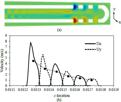
The EndoVac system, developed a local maximum of wall shear stress in the apical region of the simulated canal. However, the local maximum of wall shear stress is developed in the vicinity of the pair of micropores furthest away from the apical. This observation is attributed to the fact that more than half (i.e., ≈ 54%) of the fluid is forced to flow through these holes, as evidenced in Fig. (5a). The remaining 30% and 16% of the total flow seeps through the second and third pair of micropores, respectively. This observation is opposite to what has been observed by [17], where the most intense jet was observed to form through the pair of outlets which is closest to the apical. This is attributed to the different irrigation technique, i.e., positive in the latter while negative in the present study.
It is interesting to note that although the maximum wall shear stress developed by the EndoVac system is higher than the open-ended needle placed 0.5 mm and 1.0 mm short of the working length, the average wall shear stress along the canal wall of the latter cases was higher than the former.
Fig. (5b) presents the distribution of axial velocity through the micropores. It is noted that the average axial velocity decreases almost linearly with the distance of micropores from the needle inlet. It is also noteworthy that the peak axial velocity occurs offset from the pore central axis, particularly for the pair of micropores furthest away from the apical.
4.2. Discharge Coefficient
The discharge coefficient is an important functional parameter characterizing the irrigant exchange, which subsequently plays a crucial role in the debridement efficacy of irrigation of root canals. The discharge coefficient is determined as the ratio of the actual to the ideal rate of flow. The theoretical flow rate through the injection nozzle is represented by the steady-flow orifice equation:
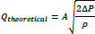 |
where Q is liquid volume flow rate, A is needle cross-section area, ρ is irrigant density and ΔP is pressure drop across the needle. Table 2 summarizes the rate of irrigant flow and discharge coefficient for the investigated irrigation system. A higher discharge coefficient means that the system can deliver a greater volume of irrigation solution to the root canal for the same aspiration power.
The discharge coefficient was found to be the highest when the mANP is placed 0.2 mm short of the working length (i.e. mANP 1). The reason for this observation is due to the existence of the highest vacuum (i.e., lowest static pressure) in the root canal, allowing a greater irrigant flow rate and thus improving the effectiveness of smear layer removal. A similar trend of more efficient irrigant exchange for needle placement closer to the working length has been reported previously [21]. This attribute is particularly important for chemically active irrigants in order to retain a high concentration of its active component at the apical part of root canals. It is also interesting to note the non-monotonic trend of the discharge coefficient with the needle placement.
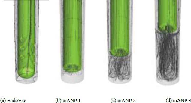
4.3. Streamlines and Irrigant Replacement
In a positive pressure method, the streamlines indicate the route of fluid particles released from the needle inlet. However, in the negative pressure method, the streamlines indicate the route of fluid particles aspirated into the needle inlet. In other words, streamlines provide information on how far the irrigant can reach the apical region. Thus, they provide information about irrigant replacement [22]. Irrigant replacement up to the apical parts of the root canal system is critical for an adequate chemical effect [23]. Thus, in this study, the EndoVac and mANP revealed streamlines capable of reaching the apical end, enhancing debris removal and indicating improved cleaning efficacy at the apical region. According to the systematic review on apical negative pressure, this technique may be more effective in removing pulp tissue remnants from the apical region of the root canal (0–1 mm from WL) [24].
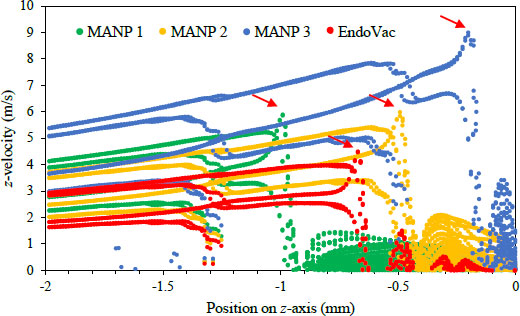
It is also interesting to note that in (Fig. 7), the irrigant replacement extended to only 0.07–0.09 mm apically to the needle tip for the mANP system. These values are comparable to the side-vented needle reported previously for the positive pressure with a similar irrigant flow rate [25]. Interestingly, there is a non-negligible z-component of irrigant velocity beyond the irrigant replacement distance.
4.4. Velocity/Flow Rate
According to Boutsioukis (2009) [25], in positive pressure conditions, an increase the inlet velocity led to more efficient irrigant replacement due to increased flow rate and magnitude velocity. However, caution must be taken since high irrigant flow rates were frequently reported as a cause of irrigant extrusion in the positive pressure method [26]. A previous study revealed that apical fluid pressure increased with fluid flow rates [27]. However, in the negative pressure method, the vacuum/aspiration pressure was already set. The irrigant flow rate was determined by the pressure gradient. It is interesting to note that the irrigant flow of the negative pressure method is aspirated into the needle, producing negative apical pressure at the apical end. As a result, it is reasonable to conclude that the negative pressure method (EndoVac and mANP) is a safer irrigation method capable of preventing irrigation extrusion.
Fascinatingly, the velocity aspirated into the needle inlet (mANP 1) showed the highest. This is in agreement with Lorono et al. [14], where the velocities near the wall increase if the space between the needle and the root canal is limited. Whereas, in the EndoVac case, the average axial velocity decreases almost linearly with the distance of micropores from the needle inlet.
4.5. Apical Pressure
It is discussed in the previous study that high apical pressure has a tendency to increase the risk of irrigant extrusion [14, 22]. However, the threshold of pressure that determines the risk of extrusion remains unknown. Both mANP and EndoVac revealed negative apical static pressure, hence the negligible risk of extrusion. Interestingly, Table 2 revealed that all mANP groups showed higher negative apical pressure values compared to the EndoVac. This might be due to the open-ended needle design (mANP) that allows irrigants to be aspirated at the apical end compared to the EndoVac, which uses a close-ended needle with micropores design. The results indicated that the closed-ended needles have lower apical pressure, whereas open-ended needles have higher apical pressure, which is in consistent with other studies [22].
Overall, this study provides a fluid dynamics perspective of two different needle designs using a negative pressure irrigation technique. According to Boutsioukis et Al. (2010), the tip design of the irrigation needle influences the flow pattern, flow velocity and apical wall pressure [17]. The study revealed an ideal flow rate for an irrigation system between 12 ml/s and 23 ml/s ( Table 2), which should be able to deliver sufficient flow and volume of irrigant to the working length without pushing the solution into the periradicular tissues [23]. Both the EndoVac and mANP systems showed the highest maximum wall shear stress at the apical region, and irrigant replacement was able to reach the apical end, indicating better cleaning efficacy at the apical area. Furthermore, the negative apical static pressure ensures that the risk of irrigant extrusion is negligible, and it is even recommended to be used as a preventive measure in the high-risk case of sodium hypochlorite accident, such as in the case of an open apex [26, 28, 29]. Therefore, as a recommendation, further research is required to evaluate the relationship between the wall shear stress magnitude, streamlines, apical pressure and the irrigation efficacy of the negative pressure irrigation technique using EndoVac and mANP.
CONCLUSION
In conclusion, CFD analysis showed different needle designs and needle depth insertion affect the irrigation dynamics pattern and magnitude. Both designs resulted in negative apical static pressure, thus indicating a negligible risk of extrusion. Streamlines of the EndoVac and mANP indicated both irrigant replacement able to reach up to the apical area. The open-ended needle design of mANP at 0.2 mm short of WL contributed to the highest wall shear stress and discharge coefficient magnitude, indicating better cleaning efficacy. However, clinically, it is not relevant to measure 0.2 mm short of the WL. Thus, it is acceptable to place the mANP needle at 0.5 mm from the WL.
LIST OF ABBREVIATIONS
| CFD | = Computational Fluid Dynamics |
| SST | = Shear Stress Transport |
| mANP | = Modified Apical Negative Pressure |
ETHICS APPROVAL AND CONSENT TO PARTICIPATE
This study was approved by the institutional research committee of the Faculty of Dentistry, Universiti Teknologi MARA, Malaysia ethical committee approval no. EC/08/2021 (MR/666).
HUMAN AND ANIMAL RIGHTS
No humans or animals were used for the studies that are the basis of this research.
CONSENT FOR PUBLICATION
Not applicable.
AVAILABILITY OF DATA AND MATERIALS
The data supporting this study's findings are available from the corresponding author [A.H] on special request.
FUNDING
None.
CONFLICT OF INTEREST
The authors declare no conflict of interest, financial or otherwise.
ACKNOWLEDGEMENTS
Declared none.