All published articles of this journal are available on ScienceDirect.

Effect of Die Materials on Marginal and Internal Adaptation of Zirconia Copings: An In Vitro Study
Abstract
Aim:
Close adaptation of cemented CAD/CAM restorations to their abutments is highly dependent on precise impressions and accurate replicas of teeth and adjacent oral tissues. This in-vitro study compared the effect of two die materials, as physical replicas of prepared teeth, on internal and marginal adaptations of zirconia copings to their corresponding abutments.
Materials and Methods:
A virtual model simulating a prepared premolar was designed and used for the milling of thirty identical metal models. Impression was taken of all models by Polyvinyl siloxane material. Fifteen impressions were poured in with Type IV stone and the other fifteen with polyurethane resin to make dies. All dies were scanned, and for each of them, zirconia coping was designed and milled. The copings were cemented to their corresponding metal models. Marginal gap between each coping and its metal model was measured at 20 points with a stereomicroscope (×60). Then the specimens were sectioned into two halves, and the internal gap was measured at seven points, including right and left cervico-axial, mid-axial, occluso-axial, and mid-occlusal. The data were analyzed with an independent T-test and repeated measure ANOVA at a 95% confidence level (p<0.05).
Results:
Mean value of marginal gap for Type IV stone and Exakto-Form groups were 54.31 ± 4.11 μm and 56.25 ± 4.24 μm, respectively. Mean values of the internal gaps for both groups ranged from 48 μm to 120 μm.
Conclusion:
Based on the results of this study, an internal and marginal adaptation of zirconia copings designed on digitized polyurethane and Type IV stone dies are clinically acceptable.
1. INTRODUCTION
Successful CAD/CAM restorations depend on accurate 3D images of teeth and adjacent tissues obtained directly by intraoral scanning or indirectly by extraoral scanning of physical replicas (casts or models) of the dental arch and surrounding tissues [1, 2]. In the latter scenario, the accuracy of virtual models relies on the accuracy of corresponding physical models. As a result, physical models must be made of materials that possess enough surface hardness, resistance to abrasion, transverse strength, dimensional stability, detail reproduction, and compatibility with impression materials [3]. Low cost and ease of use are also important parameters considered in the selection of die materials. In addition to the mentioned parameters, scannable die and model materials should also have a high smooth surface. Low surface roughness results in superior scannability [4]. The surface of the model also should not be very shiny; otherwise, the application of powder before scanning would be necessary [4].
In dentistry, high strength dental stones are widely used because of their acceptable dimensional accuracy, low cost, ease of use, and compatibility with all impression materials [5]. However, they have less than ideal detail reproduction capability with relatively poor abrasion and fracture resistance [5, 6]. Furthermore, they are heavy, bulky, and subject to fracture [7]. Dental stones cannot be used when the physical model of the digital data should be fabricated, neither by milling nor by additive technologies such as 3D printing [7].
An alternative die material is a polyurethane resin. It has good detail reproducibility, high strength, and abrasion resistance, which make it suitable for pouring impressions of tall and thin prepared teeth [6, 8]. However, in the study of Kenyon et al. on the dimensional accuracy of 7 die materials, polyurethane showed expansion in occlusocervical dimension and contraction in mesiodistal and buccolingual dimensions [5]. In their study, epoxy resin showed only contraction, and stones had just expansion. The authors concluded that such a combination of expansion and contraction in polyurethane is hard to be compensated for, and could negatively affect the seating of the full coverage CAD/CAM restorations [5]. As a result, they did not recommend it as a die material. According to Derrien and Sturtz, adding silica fillers up to 60% to polyurethane resin would reduce their transverse strength and dimensional variations during polymerization [9]. Currently, the shrinkage of resin is about 0.025% [6]. In contrast to stones, polyurethane resin can be used for fabricating physical forms of digital models either by additive or subtractive techniques [7].
Making CAD/CAM restorations based on scanned dental models have become a routine practice in dentistry. Despite the progress made in polyurethanes, dental stones are still the most widely used die material. This study aimed to compare the performance of polyurethane and Type IV stone models because there was no conclusive evidence regarding the superiority of one over the other. The evaluated parameters were marginal and internal adaptation of full coverage CAD/CAM restorations to their corresponding abutments. The close adaptation of indirect restoration to its abutment is an important factor for the success and longevity of the treatment [6]. Gaps in margin result in the dissolution of cement, rendering the tooth susceptible to caries, pulpitis, periodontal disease, and eventual tooth loss [6, 10]. Variation in fit and cement thickness can also create stress concentration with resultant reduction of strength, radial crack growth, and fracture of restoration [11, 12]. The null hypothesis of this study was that the marginal and internal adaptation of the copings designed on digitized polyurethane and Type IV stone models would be significantly different.
2. MATERIALS AND METHODS
The methodology used in the present study for assessing the effect of different die materials on the adaptation of zirconia copings was as follow:
2.1. Fabrication of Metal Models
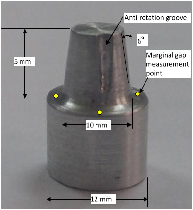
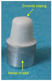
In order to have similar specimens and avoid any wearing off during different steps of the study, a virtual model simulating a prepared premolar was designed. Using this design, 30 identical aluminum models were fabricated by a milling machine (imesicore/450i, Germany). The models had 12 mm cervical diameter, 6 mm height, 6o total occlusal convergence, and 1 mm wide rounded shoulder finish line, as shown in Fig. (1). An anti-rotation groove, 1 mm deep, extended from occlusal surface to 2 mm above the finish line. Four equidistant points were marked on the periphery of the model, below the finish line, to serve as reference points during marginal gap measurements.
2.2. Making Dies
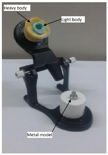
Small perforated plastic cups (20 mm diameter and 20 mm height) were used as impression trays to make polyvinyl siloxane (Panasil, Kettenbach Dental GmbH & Co. KG, Germany) impressions of each metal model. Cups were attached to the upper member of an articulator by means of magnetic rings. The metal models were attached to the lower member and centered into the middle of the cup (Fig. 2). For making impressions, light body (type 3; Panasil, Kettenbach Dental GmbH & Co. KG, Germany) was injected around the surface of the metal model, and the cup attached to the upper ring was filled with the heavy body (Putty soft, type 0; Panasil, Kettenbach Dental GmbH & Co. KG, Germany). Then the articulator was closed to allow the impression material to set. After setting, the impression was separated from the metal model. Excessive impression material was trimmed away with a scalpel. The impressions were randomly allocated into two groups of 15 each, according to the type of used die material. For the stone group, dental die stone Type IV (Ultra hard Snow Rock Die Stone, UD/Korea) was mixed according to the manufacturer’s recommended water/ powder ratio (W/P = 20 ml/100g), under 710 mm Hg vacuum for 60 seconds. The Type IV stone was vibrated into the impression and allowed to set for one hour at room temperature and humidity before removal from the impression.
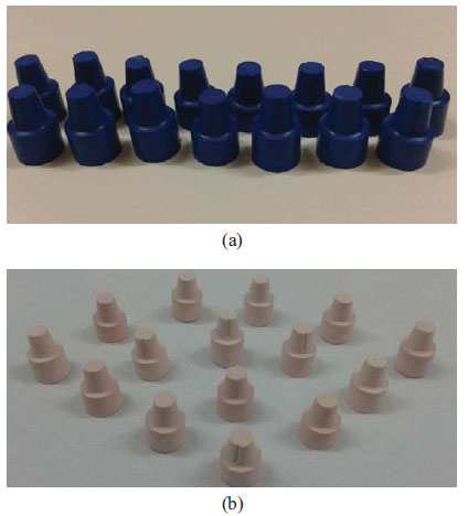
Exakto-Form (Bredent, Germany) model resin was a two-component material. Each component was stirred completely before mixing to obtain a homogenous mixture. Then component B was added to component A and mixed thoroughly for 30 seconds until the uniform color (blue) mixture was obtained and poured swiftly into the impression. After 30 minutes of mixing, the dies were removed and allowed to achieve the final set. Dies with any defects like air bubbles or imperfections were discarded and refabricated. Fig. (3) shows that the dies are made of two different materials.
2.3. Computer Aided Designing and Manufacturing of Zirconia Copings
Each die was scanned (D710 Multi Die 3D scanner,3shape A/S, Copenhagen K, Denmark) and yttria- stabilized zirconia copings were designed by 3 shape software (Cercon Art, DeguDent, Germany) to have 1.00 mm thickness at occlusal and 0.6 mm thickness at axial walls. The cement gap was set at 30 μm except for the marginal 1 mm. Cercon base light discs (Cercon, DeguDent, Germany) were used for fabrication of copings by Cercon milling machine (Cercon brain expert, DeguDent, Germany).
Before seating the copings on their respective metal models, their intaglio surface was checked for interferences by a fit checker and adjusted if necessary. Finally, all the copings were cleaned by steam cleaner.
2.4. Cementation of the Copings
Copings were cemented to their corresponding metal models with glass ionomer cement (GC: Gold label luting and lining cement, GC corporation Tokyo, Japan) using a rocking motion (Fig. 4). Immediately after removing the excess cement and in order to get a uniform load on all the specimens, the coping-metal model assemblies were placed in a chewing simulator machine (SD Mechatronik, chewing simulator CS- 4, Germany) under a constant load of 50 N for 10 minutes.
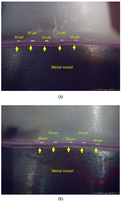
2.5. Marginal Gap Measurement
Marginal gap in the micron was determined as the vertical distance between the margin of restoration to the end of the finish line using a stereomicroscope (Olympus SZX9, Japan) with ×60 magnification. The measurements were performed at five sites between every two points already indexed on the periphery of the metal models, 20 points for each model in total (Fig. 5). The mean value of gaps for each specimen and finally for each group were determined.
2.6. Internal Gap Measurement
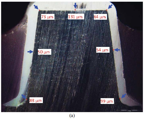
The metal model–coping assemblies were placed in a custom-made plate to be embedded inside polyester material. After setting, the polyester block was placed in a precision micro-cutting machine (Mecatome, T201 A; Presi, France), and the specimens were sectioned longitudinally into two halves under a water-cooling system.
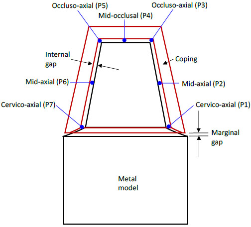
The internal gaps at the following seven points were measured under a stereomicroscope (Olympus, SZX9, Japan) at ×60 magnification for each specimen (Figs. 6 and 7).
- P1- The junction of cervical and axial wall on the right side.
- P2- The mid- axial point on the right side.
- P3- The junction of axial and occlusal wall on the right side.
- P4- The midocclusal point.
- P5- The junction of axial and occlusal wall on the left side.
- P6- The mid- axial point on the left side.
- P7- The junction of cervical and axial wall on the left side.
2.7. Statistical Analysis
Distribution of quantitative variables was evaluated graphically and statistically (with both Kolmogorov-Smirnov and Shapiro-Wilk tests), and the results showed it is normal. In order to compare the marginal gap between the two groups, an independent t-test was performed. Repeated measure ANOVA was used for comparing internal gaps at evaluated points of two groups. For comparing the difference between points within each group, the pair-wise comparison (Sidak test) was used. The level of significance was considered to be <0.05 for all statistical tests.
3. RESULTS
3.1. Marginal Gap
The mean marginal gap, standard deviation, and standard error for each group are presented in Table 1. The independent t-test did not show any significant difference between the tested groups (p = 0.80).
| Groups | N | Mean Marginal Gap (µm) | Standard Deviation | Standard Error of Mean |
|---|---|---|---|---|
| Type IV stone | 15 | 54.31 | 4.11 | 1.06 |
| Exakto-Form | 15 | 56.25 | 4.24 | 1.09 |
3.2. Internal Gap
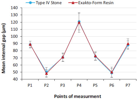
The mean internal gap, standard deviation, and standard error of internal gap for each point of the two groups are presented in Fig. (8). For both groups, the gap was about 50 µm at mid-axial points and about 120 µm at the mid-occlusal points. It ranged from 70-90µm for cervico-axial and occluso-axial points. Repeated measures ANOVA analysis did not find any interaction between die materials and evaluated internal gaps at different points.
A pair-wise comparison test with a 95% confidence interval revealed a significant difference (P = 0.00) between different points within each group. The mid-occlusal points (P4) had significantly higher gaps than any other point. The points at the junction of the cervical and axial wall (P1, P7) had significantly more gaps than points at the junction of the axial and occlusal wall (P3, P5). Significantly less gap was found at mid-axial points (P2, P6). The difference between the right and left sides of each point (P1 and P7; P2 and P6; P3 and P5) was not significant (P = 0.100).
4. DISCUSSION
The results of the present study showed no significant difference in the fit of zirconia copings designed on digitized polyurethane resin or Type IV stone dies. Therefore, the null hypothesis was rejected.
In this study, conventional Type IV stone was examined rather than special stones designed for scanning because conventional stones are still in use in many dental laboratories. Two main features of scannable stones are their very smooth surface and lack of shine [4]. According to Kim et al., surface roughness of stone models have a decisive effect on the precision of fit of zirconia cores [4]. It means that the rougher the surface of the model, the higher the marginal gap. However, they did not find any significant difference between the surface roughness of scannable and ordinary model stones [4]. It is suggested that the impression material has more impact on the surface roughness of models than the kind of gypsum product [13]. On the other hand, the authors of the present study had examined the surface roughness of Snow Rock and Exakto-Form and found significantly higher values for Snow Rock [14]. But the results of the present study showed no significant difference between marginal or internal gaps of the two groups. Similar results are also reported by Lillywhite and Rahme [6, 15]. It is probable that other factors, like the dimensional accuracy of materials, are more influential on the adaptation of CAD/CAM restorations than the surface roughness.
In this study, opacifying powder was not applied to the surface of dies before scanning by 3Shape lab scanner. According to Alghazzawi et al., when a laboratory 3Shape scanner is used, the imaging powder is not required for scanning die stones [16].
In this study, the marginal gap for the stone group was insignificantly smaller than the polyurethane group. Kenyon and Derrien reported less dimensional accuracy and greater dimensional variations for polyurethane resin in comparison with Type IV stones [5, 9]. However, polyurethane has shown less dimensional changes when filled up to 60% with silica filler [9]. This might explain the insignificant difference between the results of the two groups in the present study, though the amount of filler within Exakto-Form is not clear. Rahme et al. also compared the marginal gap of Procera copings cemented on their respective stone or polyurethane dies [15]. Unlike the present study, they consistently found larger marginal gaps for the Type IV stone group. From the results of the two studies, it can be concluded that the polyurethane dies, perhaps because of their smoother surface are scanned more accurately. So, the adaptation of the crowns to the polyurethane dies is better than to the Type IV stone dies. On the other hand, when the crowns are cemented on their respective abutments, the adaptation for the stone group is better. According to Da Silva, Polyurethane resin shows significantly greater shrinkage than plaster Type IV [17]. The same is reported by Lillywhite [6]. It is believed that small expansion (0.09%) of Type IV stone dies is more beneficial to the seating of indirect CAD/CAM restorations on their abutments than small contraction (0.025%) of polyurethane dies [5, 9]. Regarding the clinical importance of the results, the mean marginal gap was under 60 µm for both groups and well below the range of acceptable gap (120 µm) suggested by McLean and Fraunhofer [18]. It should be emphasized that after firing of veneering layer, an increase in the marginal gap is highly probable [12, 19].
In the present study, the internal adaptation of the two experimental groups did not show any significant difference. However, the difference between various locations within each group was significant. An ideal internal adaptation enhances the strength, resistance, and retention of all ceramic crowns. The factors that may affect the misfit of conventional CAD/CAM restorations are the type of restoration, the impression material, the die material, the provided cement space, the wax up and investing procedures, and the layering technique [20, 21]. In the present study, the largest gap was found at the occlusal surface rather than axial walls. The same is reported by Persson, Yang, Miura, Souza, and Ortorpa et al. [1, 22-26]. In the CAD/CAM restorations, the precision of the data acquisition system, the capability to combine and match images, the designing software, the milling machine, and the machine’s bur size must be added to the list [10, 27, 28]. The size of the milling bur is important because the width of the intaglio surface could not be smaller than the smallest bur of the milling machine [29, 30]. Therefore, a larger misfit at the occlusal surface is expected than at the axial surfaces. Reich et al. suggested that the spacer setting could be changed according to the abutment’s shape. If there are any sharp edges, for instance, at the axio-occlusal turn, thus greater space settings could be supplied [11, 31]. Also, it seems when the tip of the milling bur becomes rounder with a higher edge radius than that at the junction of the occlusal and axial surfaces, the gap at that area could be higher than the cement space. In the present study, the difference between the right and left points of each location was not significant (between points P1 and P7; P2 and P6; P3 and P5). The reason could be the symmetry of the preparation all around. The axial surfaces of the natural teeth are not symmetrical, so the measurements could be different at different axial walls.
A variety of methods are used to evaluate the marginal adaptation of dental CAD/CAM restorations, such as direct viewing, cross section view, impression replica technology, laser videography, profilometry, x-ray microtomography, three-dimensional (3-D) superimposition analysis, and clinical examination [32- 34]. Although in the cross-sectioning technique used in this study, the models have to be sacrificed, the measurements are more accurate and repeatable [35]. It should be noted that when measuring the position of the internal gap in the metal model–coping assemblies, errors could arise due to the cutting operation. Utilizing a water jet cutter in this study had several advantages, such as the ability to cut the materials without interfering with its inherent structure as there was no “heat-affected zone” [36]. Also, it produced an excellent edge quality, which decreased the time required for polishing the surfaces as there was a few or no saw-induced metal flash or smearing, which are generally found in the traditional saw cutting technique [37].
This study examined the adaptation of a single crown and did not find a significant difference between Type IV stone and polyurethane die materials. However, the difference might be significant if multiple unit CAD/CAM restorations are evaluated. So further studies on bridge abutments are suggested.
CONCLUSION
Based on the results obtained, it can be concluded that:
- There is no significant difference in the internal and marginal adaptation of zirconia crowns designed on digitized Type IV stone or the Exakto-Form polyurethane dies.
- Regardless of die material, the gap at occlusal surfaces was significantly higher than axial surfaces.
- Exakto-Form polyurethane resin can be used as an alternative die material in CAD/CAM restorations.
ETHICALS APPROVAL AND CONSENT TO PARTICIPATE
Not applicable.
HUMAN AND ANIMAL RIGHTS
Not applicable.
CONSENT FOR PUBLICATION
Not applicable.
AVAILABILITY OF DATA AND MATERIALS
The data supporting the findings of this study are available within the article.
FUNDING
None.
CONFLICT OF INTEREST
The authors declare no conflict of interest, financial or otherwise.
ACKNOWLEDGEMENTS
This study was conducted and presented as Ph.D. Research thesis in Tehran University of Medical Sciences, School of Dentistry.