All published articles of this journal are available on ScienceDirect.
Porosity Pattern of 3D Chitosan/Bioactive Glass Tissue Engineering Scaffolds Prepared for Bone Regeneration
Abstract
Aim:
The study was conducted to investigate the obtained external and internal porosity and the pore-interconnectivity of specific fabricated bioactive composite tissue engineering scaffolds for bone regeneration in dental applications.
Materials and Methods:
In this study, the bioactive glass [M] was elaborated as a quaternary system to be incorporated into the chitosan [C] scaffold preparation on a magnetic stirrer to provide bioactivity and better strength properties for the attempted composite scaffolds [C/ M] of variable compositions. The homogenous chitosan/bioactive glass mix was poured into tailor-made cylindrical molds [10cm×10cm]; a freeze-dryer program was used for the creation of uniform and interconnected macropores for all prepared chitosan-based scaffolds. The morphology of fabricated chitosan [C] and chitosan-bioactive glass [C/ M] composite scaffolds was studied by a scanning electron microscope [SEM] and a mercury porosimeter. In addition, the in-vitro biodegradation rate of all elaborated scaffolds was reported after immersing the prepared scaffolds in a simulated body fluid [SBF] solution. Furthermore, for every prepared scaffold composition, characterization was performed for phase identification, microstructure, porosity, bioactivity, and mechanical properties using an X-ray diffraction analysis [XRD], an X-ray Fourier transfer infrared spectroscopy [FTIR], a mercury porosimetry, a scanning electron microscopy [SEM] coupled to an energy-dispersive X-ray spectrometry [EDS] and a universal testing machine, respectively.
Results:
All the prepared porous chitosan-based composite materials showed pore sizes suitable for osteoblasts seeding, with relatively larger pore sizes for the C scaffolds.
Conclusion:
The smart blending of the prepared bioactive glass [M] with the chitosan matrix offered some advantages, such as the formation of an apatite layer for cell adhesion upon the scaffold surfaces, the reasonable decrease in scaffold pore size, and the relative increase in compressive strength that were enhanced by the incorporation of [M]. Therefore, the morphology, microstructure, and mechanical behavior of the elaborated stress loaded biocomposite tissue engineering scaffolds seem highly dependent on their critical contented bioactive glass.
1. INTRODUCTION
For tissue engineering [TE], naturally derived polymers have been proposed and preferred in most variable recent studies. After cellulose, chitin is considered the most abundant polymer widely present in crustaceous shells, e.g., shrimp and crabs; evidently, chitin forms intermolecular and intra-molecular strong hydrogen bonds that are hardly broken by most common solvents. Therefore, the limitation of chitin utilization as a natural polymer resource had been reported, and the majority of chitin implementations were mainly in the form of chitosan [1].
Chemically, chitosan as chitin derived cationic polymer, is composed by copolymerization of β [1→4] glucosamine with N-acetyl-d glucosamine. In recent biomedical and clinical applications, although the biological and physicochemical properties of chitosan have proven it as an excellent biomaterial for the preparation of drug delivery devices and development in various human tissues such as skin, cartilage, or bone, the processing of chitosan is restricted in tissue engineering applications, as it is usually based on a diluted acetic acid solution [2]. Chitosan has been processed in various forms to be implemented in several tissue engineering purposes, e.g., two-dimensional [2D] membranes [3], nanoparticles [4], three-dimensional [3D] fiber meshes, or polymer fibers [4, 5]. Moreover, various studies have reported chitosan as a successful drug delivery carrier [6, 7]. In addition, chitosan-based scaffolds are used as ingenious delivering systems, capable of carrying many biomolecules, and active ingredients like growth factors [8]. Many preparation methods have been developed for chitosan involving supercritical fluid aided phase inversion technique, freeze-drying process, and lyophilization of chitosan gel solution [9-11].
Bone tissue engineering assembles isolated functional cells with a 3D biocompatible and biodegradable scaffold synthesized from engineered biomaterials, aiming to regenerate diseased or damaged bone tissues. Teams of multidisciplinary scientists have been working on smart design and elaboration of TE scaffolds for optimum cell seeding and proliferation and the investigation of the in vivo and in vitro TE constructs [12]. Currently, bioactive glasses and their related composites represent the most successful scaffold compositions for bone TE. Those 3D structures are highly porous scaffolds, exhibiting well-tailored pore size, homogenous porosity, and interconnectivity among the pores [13].
Bioactive glasses are a subcategory of inorganic bioactive materials; therefore, they can react with physiologic body fluids forming tenacious bone tissue bonds. This is achieved by developing a surface bone-like hydroxyapatite precipitated layer and biological interaction of tissue collagen with that bioactive substance [14]. These surface reactions on bioactive glasses provoke ion release and precipitation for critical concentrations of Na+, Ca+2, Si+4, and P+3soluble ions, therefore enhancing biological extracellular and intracellular tissue response and leading to accelerated osteogenesis [15]. Diverse TE scaffold preparation techniques have been reported in many types of research, such as thermally induced phase separation, foam replication, textile and foam coating as well as variable biomimetic trials in order to optimize microstructure, physicochemical and mechanical integrity for the TE scaffold constructs [16-18].
In vitro and in vivo challenges have been addressed with the design and fabrication of bioactive TE scaffold and the engineering of tissue constructs. In this study, a variety of 3Dbioactive chitosan-based composite scaffolds have been prepared for bone TE, and their microstructure, porosity pattern, and relevant physicochemical characteristics have been discussed.
2. MATERIALS AND METHODS
2.1. Materials
Materials used in the study were Chitosan poly [D-glucosamine] powder form from shrimp shells [medium molecular weight, deacetylated chitin 75-85%, viscosity 200-800 cP], Sigma-Aldrich company [St. Louis, MO, USA]; 448877-50G, Bioglass, laboratory of faculty of chemistry, Rennes university1, France; Acetic acid [C2H4O2] [99.8%], Sds company, France [Pyongtack, Gyeonggi, South Korea]; P0070515 LOT: P0E022250E, Sodium hydroxide [NaOH], Sds company, France [Pyongtack, Gyeonggi, South Korea]; Simulated body fluid [SBF], laboratory of faculty of chemistry, Rennes university1, France; and Potassium bromide [KBr] from Sigma-Aldrich corporation [St. Louis, MO, USA], CASNº: 7758-02-3.
The equipment utilized was Lyophilizer, Bio block Christ, Alpha 1-2 LD plus, Sciquip. Co. UK; incubator, Memmert, Single DISPLAY, Universal oven UN / UF / UNplus / UFplus, German; Panalytical XPERT PRO powder diffractometer, D 8 Advance, Karlsruhe, Germany; Fourier transformed infrared spectroscopy [FTIR], Bruker Equinox 55Corporation, International Equipment Trading [IET], Vernon Hills, Illinois 60061 USA; mercury intrusion pore sizer, Model: 9320 V2.08, Micrometrics Inc., USA; and scanning electron microscope [SEM], Jeol company JSM 6301, Japan.
2.2. Methods
2.2.1.1. Fabrication of 46S6 Bioactive Glass [M]
The composition of 46S6 bioactive glass powder with 46% SiO2, 24% CaO, 24% Na2O, and 6% P2O5 in weight percentage, was elaborated by melting technique and rapid quenching. The chemical reagents used for the synthesis of bioactive glass were as follows: calcium silicate, Ca2SiO4 [molecular weight [MW] = 233-250 Alfa Aesar, Germany], sodium meta silicate pentahydrate, Na2SiO3.5H2O [MW = 212.1, Sigma, Germany], and trisodium tri-metaphosphate, Na3P3O9 [MW = 305.9, Sigma, Germany]. Those substances were weighed and blended with a mechanical mixer for two h and then were pre-heated at 200ºC/2h.
Afterward, the mix was transferred to an Rh-Pt crucible to be melted following that firing regime: firing up to 900ºC/1h at a rate of 10ºC/min, then heating at 1300ºC/3h at a rate of 20ºC/min. Finally, in a regulated muffle furnace, the molten mixture was transferred into a pre-heated brass mold of 500 ºC for annealing near its glass transition temperature, aiming to relieve the residual mechanical stresses. Moreover, that muffle furnace was programmed to gradually cool at a slow rate of one ºC/min to room temperature. Produced bioactive glass [M] was mechanically ground in an agate mortar and was sifted at a grain size lesser than 62 µm [19].
2.2.2. Chitosan /Bioacive Glass Composite Scaffold Preparation
Chitosan solution as natural polymeric material was prepared from medium molecular weight chitosan powder that was extracted from shrimp shells [MW= 480.000 and degree of acetylation [DA]= 85%]. The chitosan powder was dissolved on a magnetic stirrer at room temperature in a 1% acetate solution. A produced homogenous chitosan solution was poured into custom made cylindrical Teflon molds [10mm diameter×10mm thickness] for obtaining the chitosan scaffold [C] composition. The same chitosan solution was again elaborated as a polymeric dispersion medium for compositional preparation of different proportions of composite scaffolds, where the bioactive glass was gradually added as a dispersed phase.
A thermally induced phase separation [TIPS], i.e., Freeze-drying technique, was implemented in order to elaborate C as well as biocomposite scaffolds with four different compositional proportions of chitosan [C]/bioactive glass 46S6 [M], which was prepared in the laboratory by melting method. Those fabricated four other compositional scaffold groups were C, 1C:1M, 1C:2M, and 2C:1M by weight. Finally, the scaffolds were dried inside an incubator adjusted at 37°C before proceeding to their physicochemical characterization.
2.3. Physicochemical Characterization of the Fabricated Chitosan-based Scaffolds
A factorial design was performed for the physicochemical characterization tests of the constructed chitosan-based scaffolds, where n=five. The differently prepared biocompo- sites [C, 1C:1M, 1C:2M, and 2C:1M] were investigated with the aid of XRD analysis and Fourier transformed infrared spectroscopy [FTIR] for detection of phases and molecular structures of prepared scaffolds, respectively. In addition, microstructural analyses of those scaffolds were accomplished using a scanning electron microscope [SEM] to study their external and internal micro-morphologies.
2.3.1. X-ray Diffraction Analysis [XRD]
XRD patterns of the various fabricated chitosan-based scaffolds [C, 1C:1M, 1C:2M, and 2C:1M] were achieved to identify the existing crystalline phases in the constructed bio compositions and to track the alterations that might develop in the structural characteristics of those biomaterials. As the pure 46S6 bioactive glass, the XRD pattern of pure hydroxyapatite was essentially established. A Panalytical XPERT PRO powder diffractometer was used with wide-angle [WA] XRD patterns for analysis of the different synthesized biocomposite scaffolds. The scaffolds XRD were performed using Cu Kα radiation and operated at an electrical voltage of 40 kV at room temperature. The scaffold XRD patterns were investigated at angle 2 ϴ with a range of 5-60 º, scanned at a speed of 2º/ min., and data of the XRD analysis were computed based on Bragg’s equation [20]:
n λ = 2 d sin ϴ
Where, n = an integral number
λ = wave length
d = interplanar spacing
ϴ = diffraction angle
2.3.2. Fourier Transformed Infrared Spectroscopy [FTIR]
FTIR identified functional groups of elaborated different biocomposite scaffold compositions [C, 1C:1M, 1C:2M, and 2C:1M] and the intermolecular interaction between the components in each scaffolding system. For each prepared scaffold composition, two milligrams of powder were mixed with 198 mg KBr [potassium bromide] powder press to give 1% concentration, which was suitable for obtaining proper IR transmission spectral curves. The mixtures were then subjected to 8 tons /cm2 load to get the required discs with a resolution of 2 cm-1. FTIR collected spectra were detected to be ranging between 400 and 4000 cm-1.
2.3.3. Scanning Electron Microscopic Analysis [SEM]
All chitosan scaffolds [C, 1C:1M, 1C:2M, and 2C:1M] were coated with a gold-palladium layer for the examination of surface morphology as well as microstructure of the different scaffolds using the scanning electron microscope [SEM].
2.3.4. Porosity Measurement
Mercury intrusion pore sizer [MIP] was used as a porosimeter to evaluate the 3D pore structure of the different synthesized [C, 1C:1M, 1C:2M, and 2C:1M] scaffolds. Mercury had a contact angle with the specimen's material being more significant than 90°.
2.3.5. Steps of the Porosity Testing
Before placement in the glass bulb of the penetrometer, the scaffolds were weighed [Ws]. Applying a low-pressure cycle, the capillary stem and the space around the specimen were filled with mercury [Hg]. Mercury was then gradually forced into the specimen's pores during the high-pressure cycle, in which the pressure was raised up to 207 MPa [30.000 psia]. The Hg volume penetrating into the pores was identified by monitoring the level of the receding Hg column in the capillary stem while raising the pressure [21]. Afterward, envelope [Bulk] density, apparent density, and percent porosity of the prepared different scaffold compositions were calculated as follows:
Scaffold’s envelope [Bulk] density [ρse] was determined by dividing the initial scaffold’s weight [Ws] by the scaffold’s envelope volume [Vse], which was the total volume of the specimen, including the volume of its open pores. At the end of the low-pressure cycle, Vse was obtained by subtraction of the volume of Hg present in the penetrometer [VHg] from total penetrometer volume [Vp]. Envelope density for each scaffold composition was calculated from the following equation:
ρse= Ws/ Vse = Ws/ [Vp - VHg][22]
Where, ρse; specimen's envelope density
Ws: specimen’s weight
Vse: specimen’s envelope volume
Vp: total penetrometer volume
VHg: volume of mercury in penetrometer.
Scaffold’s apparent density [ρsa] was identified by dividing the initial scaffold’s weight [Ws] by its apparent volume [Vsa], which was the volume of the scaffold per se after excluding the volume of its open and interconnected pores. Then, the scaffold's apparent volume was identified by subtracting the volume of Hg that filled the scaffold's connected pores [V] from the specimen's envelope volume [Vse]. At the end of the high-pressure cycle, Hg volume penetrating into the open pores [V] corresponded to the volume of Hg that receded from the capillary stem. Thus, the scaffold's apparent density was determined from the following equation:
ρsa = Ws / Vsa = Ws/ [Vse– V] [22]
Where, ρsa: scaffold’s apparent density
Ws: scaffold’s weight
Vsa: scaffold’s apparent volume
Vse: scaffold’s envelope volume
V: volume of mercury into open pores.
Percent porosity of each scaffold was calculated from envelope density [ρse] and apparent density [ρsa] according to the following equation:
Percent porosity = {1- [ρse / ρsa]} 100 [22]
Where: ρse: scaffold’s envelope density
ρsa: scaffold’s apparent density.
In order to determine the scaffold's pore volume distribution [i.e., incremental intrusion versus pore diameter], the Hg pressure was gradually increased until the high-pressure cycle aimed to force the Hg into the scaffold’s open pores. Washburn equation [23, 24] correlated the entry diameter of the intruded pore [D] with the applied pressure that forced Hg into that pore [P]:
D = - 4 µ cos θ / P
Where, D: entry diameter of scaffold pore
µ: surface tension of Hg [485 dynes/cm] [23]
θ: mercury’s contact angle on scaffold’s surface [130o] [24]
P: applied pressure
Since both surface tension and Hg’s contact angle were constant, each pressure value corresponded to a pore diameter calculated from the Washburn equation. Then, an incremental intrusion versus diameter curve was plotted, describing the distribution of the total pore volume distribution over the pore diameter range and determining at which diameter the pore volume was mostly concentrated [22].
2.3.6. Compressive Strength
At room temperature, uniaxial compression tests were carried out for all scaffold compositions [C, 1C:1M, 1C:2M, and 2C:1M] [thickness ~3 mm and diameter ~8 mm] by a computer-controlled Universal testing machine at a static load cell of 5 KN and at a crosshead speed of 1mm/min until failure. Obtained data were recorded through computer software. Moreover, the maximum failure load of each scaffold was recorded in N, and the compressive strength value was computed from the peak load record divided by scaffold specimen surface according to the following equation [25]:
Compressive strength [CS] = 4P/πd2
Where, P: load [in N] at the fracture point
d: diameter [in mm] of the cylindrical specimen
Compressive strength values of different scaffolds were collected, computed, and were calculated in MPa, and then statistically analyzed as means ± standard deviation [SD].
2.3.7. Ex- vivo Biodegradation in SBF for the Different Chitosan-based Scaffolds
Ex vivo biodegradation for all scaffold biomaterials [C, 1C:1M, 1C:2M, and 2C:1M] was investigated by immersing each scaffold individually in a simulated body fluid [SBF] solution. In the chemical laboratory, freshly prepared SBF solution was elaborated by the homogenous dissolution of NaHCO3, NaCl, K2HPO4.3H2O, KCl, CaCl2, and MgCl2.6H2O in de-ionized water. Afterward, the elaborated SBF solution was buffered using Tris-buffer [CH2OH]3 CNH2 and HCl [6M = 6mol/L] to adjust the pH at 7.4; therefore, the composition of the prepared SBF solution was simulating that of human blood plasma Table 1 [26].
| Ionic concentrations [10-3mol.L-1] | |||||||
|---|---|---|---|---|---|---|---|
| Na+ | K+ | Ca+2 | Mg+2 | Cl- | HCO-3 | HPO4-2 | |
| SBF | 142 | 5 | 2.5 | 1.5 | 148.8 | 4.2 | 1 |
| Plasma | 142 | 5 | 2.5 | 1.5 | 103.0 | 27.0 | 1 |
2.3.8. Statistical Analysis
Numerical data of the elaborated study were presented in the form of means and standard deviation [±SD] statistical values. The One-way ANOVA test was implemented for comparison between the different scaffolds [C, 1C:1M, 1C:2M, and 2C:1M]. Repeated measures ANOVA test was applied to investigate the time-dependent changes within each scaffold. Tukey’s post-hoc test was applied for pair-wise comparisons, whenever the ANOVA test was found significant. Kruskal-Wallis test was carried out for comparison between the fabricated scaffolds. Mann-Whitney U test was performed for studying pair-wise scaffold comparisons, when obtained; the results of the Kruskal-Wallis test were found to be significant. Friedman’s test was also used to monitor the changes within each scaffold over time. Moreover, Wilcoxon signed-rank test with Bonferroni’scorrection was implemented for pair-wise scaffold comparisons in case of significant Friedman’s test findings. The significance level was defined at P ≤ 0.05. Statistical analysis was conducted using IBM [IBM Corporation, NY, USA] SPSS[SPSS, Inc., an IBM Company] Statistics Version 20 for Windows.
3. RESULTS
Four types of chitosan-based scaffolds were prepared by freeze-drying technique [C, 1C:1M, 1C:2M, and 2C:1M], and it had been noted that increasing the bioactive glass [M] concentration increased the chitosan [C] hydrogel’s viscosity.
3.1.1. X-ray Diffraction Analysis of Scaffolds [XRD]
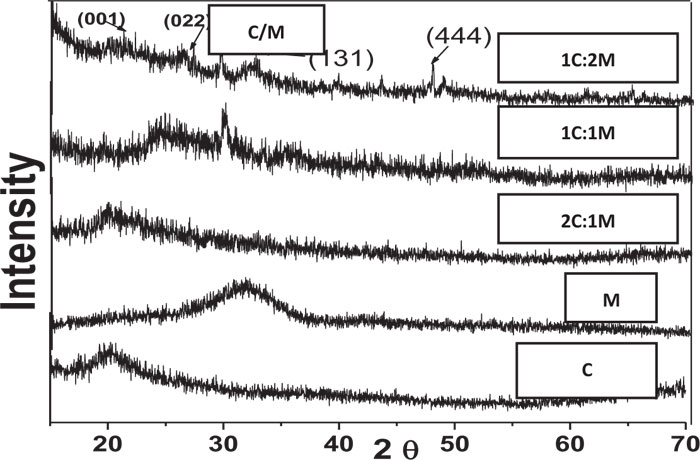
XRD analysis of scaffolds was carried out for the detection of existing crystalline structures in prepared dried chitosan-based scaffolds. Their XRD patterns were graphically presented with those for C and M as references before scaffold immersion in SBF. Detected peaks for chitosan and synthesized 46S6 bioactive glass [M] were matching their JCPDS [Joint commission for powder diffraction standards] numbers of the International center for diffraction data [ICDD] standard (Fig. 1).
Before immersion in SBF, pure C scaffolds showed some diffraction bands that identified them as a semi-crystalline structure with the formation of randomly oriented crystals, which might be due to the high concentration of hydroxyl [OH] groups. Characteristic Bioactive glass [M] presentation was a diffraction halo found between 20° and 37° [2θ], where its center was at 32°, confirming that M existed as an amorphous structure (Fig. 1). For the prepared biocomposite scaffolds, five peaks were detected showing semi-crystallinity at 2θ of 21.23°[001], 26.08°[022], 27.34°, 39.59°[131] and 47.81°[444] that might be due to bioactive glass-chitosan polymer combination. Those detected peaks indicated a certain degree of biopolymer network crystallinity that was notably decreasing with increasing M content all over the various scaffold compositions (Fig. 1).
Pure synthetic HA was considered a reference to track apatite formation to prove the proper ex vivo bioactive composition. Concerning syntheticHA, the peaks were found to match the ICDD standard for HA [JCPDS 09-432]. Thus, the maximum peak of HA with relative intensity [I/I°] of 100% was detected at 2θ = 31.92° and d= 2.80. Other peaks of HA were observed at 2θ = 26.09°, 49.7°, 34.2°, 46.9° and 39.9° that corresponded to the relative intensities [I/I°] of 68.43%, 38.32%, 36.35%, 31.38%, and 27.04% and d values of: 3.41, 1.83, 2.61, 1.93 and 2.25, respectively (Fig. 2).
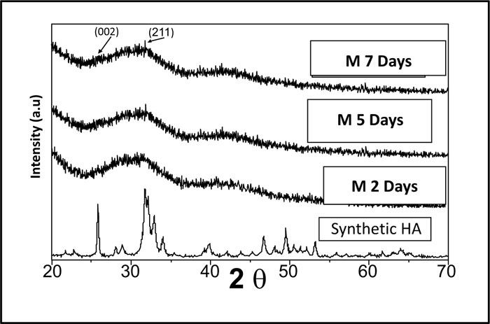
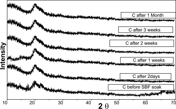
XRD pattern of C scaffolds before and after soaking in SBF showed no apatite formation on C scaffold surfaces after two days, one week, two weeks, three weeks, and one month of immersion in SBF (Fig. 3). Besides, XRD patterns of M after 2 and 5 days of scaffold immersion in SBF did not identify any characteristic peak of that of hydroxyapatite [HA]. However, seven days after soaking in SBF, only two HA characteristic peaks were observed at 25.80°and 31.79°, which proved successful ex-vivo bioactivity of 46S6 bioactive glass [M] that was elaborated by melting technique (Fig. 2).
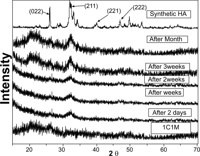
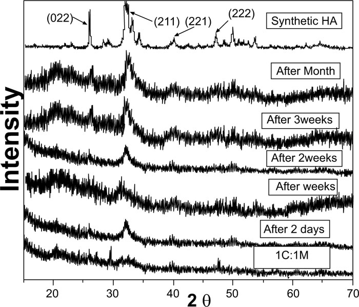
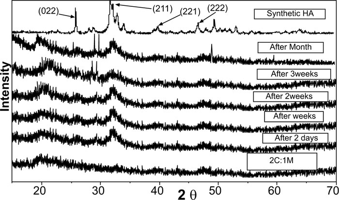
Evidently, after soaking in SBF for two days, one week, two weeks, three weeks, and one month, XRD patterns of biocomposite [1C:1M, 1C:2M, and 2C:1M] scaffolds showed three sharp diffraction peaks; 25.88°, 31.8°, 39.89° and 46.7° [2θ]. Those observed diffraction peaks were attributed to [022], [211,221,222] reticular planes of HA as reference. The noted gradual increase in the intensity of the detected peaks from the 2ndday to the 30th day indicated the progressive rise in HAdeposition. Moreover, obtained XRD patterns confirmed that HA deposition on scaffold surface increased with more amount of M content in scaffold composition Figs. (6-4).
In comparison to the three C/M compositions, the halo of the 1C:2M scaffold composition was the highest of all biocomposite preparations because it had the relatively highest proportion of bioactive glass (Fig. 6).
3.1.2. Fourier Transformed Infrared Spectroscopy [FTIR]
Prior to immersion in SBF, frequencies of transmittance bands of the FTIR spectra of 46S6 bioactive glass [M], chitosan [C], 1C:1M, 1C:2M, and 2C:1M powders together with their structural assignments are presented in Table 2. All their collected IR spectral curves were performed between 400 and 4000cm-1 at a 2cm-1resolution before soaking in SBF Fig. (7).
The prepared M, IR spectral curve showed seven prominent characteristic transmittance bands. At about 467 cm-1, the first band was distinctive for angular stretching vibration in Si-O-Si bonding among SiO4 tetrahedrons in silicate. At 600 cm−1, the second band was attributed to phosphate groups [PO4−3], while, the third band at 740 cm−1was characteristic of [PO], and the fourth band at 945 cm−1 was attributed to SiO2 stretching bands. Furthermore, the fifth and the sixth FTIR bands at 1045 cm−1 indicated the stretching band of the phosphate group [PO2−] with SiO2. Lastly, the seventh band at 3460 cm−1 was characteristic for Si-OH (Fig. 7) [27, 28].
Regarding the chitosan [C] group, the IR curve presented transmittance bands from 3000 to 4000 cm-1 due to the stretch vibration of -NH2 and -OH groups (Fig. 7, Table 1). Characteristic bands appearing at 1657, 1597, and 1320 cm-1presented absorption bands of amides I, II, and III, respectively. Bands observed at 2926 cm-1, 2880 cm-1and 665 cm-1 corresponded to the -CH- bending vibrations. A characteristic band at 1380 cm-1was attributed to the stretch vibration of methyl groups, which were present in residual acetyl-amido groups of chitosan due to incomplete deacetylation of the parent chitin. Concerning the band at 1422 cm-1, it was characteristic for C-OH group bending vibration. Besides, characteristic bands at 1075cm-1 and 1033 cm-1 corresponded to skeletal vibrations of the C-O stretching. However, the two transmission bands at 1153 cm-1and 890 cm-1 interpreted the stretch vibrations of C-O-C groups in the chitosan saccharide structure [29-31].
| IR Wave Number [cm-1] | IR Assignment | Molecule Abbreviation | ||
|---|---|---|---|---|
| 46S6 Bioactive Glass [M] | Chitosan [C] | |||
| 467 | ……. | 467, 1200 | Bending | Si–O–Si |
| 600 | ……. | 567, 607, 1070 | [PO43-] | |
| 740 | ……. | 1030 | [PO] | |
| 945 | ……. | ……. | Symmetric stretching | SiO2 |
| 1045 | ……. | ……. | Asymmetric stretching | [PO2−] with SiO2 |
| 3460 | ……. | ……. | Stretching | Si-OH |
| ……. | 1320 | ……. | Bending | amide III |
| ……. | 1597 | ……. | amide II | |
| ……. | 1657 | 1580 | amide I | |
| ……. | 665 | 2889 | -CH- | |
| ……. | 2880 | -CH- | ||
| ……. | 2926 | ……. | -CH- | |
| ……. | 1380 | ……. | Stretching vibration | CH3 |
| ……. | 1422 | ……. | Bending | C-OH |
| ……. | 1033 | 1637 | Stretching vibration | C-O |
| ……. | 1075 | 1070 | C-O | |
| ……. | 890 | C-O-C | ||
| ……. | 1153 | C-O-C | ||
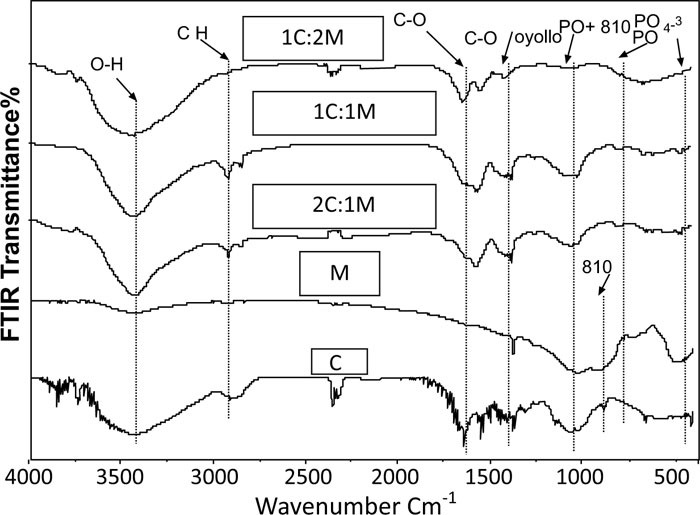
Therefore, IR spectral curves of the fabricated C/M biocomposite scaffold compositions showed several characteristic bands shifted, deformed, or disappeared, which might be attributed to specific chemical interactions between C and M (Fig. 7) [30, 31].
3.1.2.1. Ex-vivo Bioactivity Assessment
FTIR structural analysis of developed apatite layer in SBF:
After soaking in SBF, the frequencies of transmittance bands obtained in IR spectral curves of chitosan [C], 46S6 bioactive glass [M], 1C:1M, 1C:2M, and 2C:1M powders together with their structural assignments have been assembled in Table 3. The IR spectral curves of C, M, and C/M biocomposites after immersion in SBF solution for different times are graphically presented in Figs. (8a-c). IR spectral curves of synthetic hydroxyapatite [HA] were set as the reference for the assessment of structural evolutions and ex-vivo bioactivities of the elaborated scaffold biocompositions [31, 32]. The mainly observed IR transmittance bands of synthetic HA were [PO4]3 -:565, 603, 1039 cm-1 and [CO3]2-:874, 1420 cm-1 [14]. IR spectral curves of C scaffolds showed no apatite formation until one month of immersion in SBF Fig. (8a). Concerning IR spectral curves of M powder, the SiO2 band at 945 cm-1 was not obviously defined after two days or even seven days of immersion in SBF but rather poorly detected by low intensity (Table 3, Fig. 8b).
After scaffold immersion in SBF, initial characteristic bands of C/M biocomposites interfacial reactions occurring between those bioactive materials and the SBF physiologic soaking solution. Consequently, IR spectral curves of those biomaterials revealed the gradual development of new IR spectral bands (Table 3, Fig. 8c).
| IR Wavenumber [cm-1] | were strongly modified, due toIR Assignment | Molecule Abbreviation | |||
|---|---|---|---|---|---|
| HA | Bioactive glass 46S6 [M] | Chitosan [C] | C/M Biocomposites | ||
| 565, 603, 1039 | ……. | ……. | 565, 603, 1039 | Bending | [PO43-] |
| 565, 603, 1039 | ……. | ……. | 565, 603, 1039 | ||
| 565, 603, 1039 | ……. | ……. | 565, 603, 1039 | ||
| 565, 603, 1039 | ……. | ……. | 565, 603, 1039 | ||

After two days of immersion in SBF solution, the IR spectral curve of M was still not yet presenting the characteristic bands for apatite formation. Therefore, those observed findings highlighted the rapid evolution of carbonated hydroxyapatite layers on all surfaces of C/M scaffold biocomposites. At 565 cm–1, 603 cm–1, and 1039 cm–1, IR spectral curves of C/M biocomposite scaffolds showed three new, well-defined phosphate bands, which were assigned to stretching vibrations of PO4 3– groups in phosphate crystalline structures, proving the development of calcium phosphate layers. Furthermore, the IR spectrum of that calcium phosphate layer appeared quite similar to that of HA except for the 2 bands presented at 1620 cm–1and 3423 cm–1. Those exception bands were attributed to water inclusion that exhibited the hygroscopic features of the developed apatite layer (Table 3, Fig. 8c) [32].
Characteristic bands of carbonated hydroxyapatite [[PO4]3 -:565, 603, 1039 cm-1and [CO3]2-:874, 1420 cm-1] were clearly observed in IR spectral curves of M and C/M scaffold biocomposites two weeks after soaking in SBF solution. Therefore, those spectral curves had confirmed the proper crystallization of the developed apatite layers on surfaces on C/M scaffold biocomposites. The observed carbonate band at 1420 cm–1 was attributed to stretch vibration in the C−O bonds of carbonate groups, indicating the formation of layers of carbonated hydroxylapatite [CHA] on the C/M biocomposite surfaces. Obtained findings highlighted rapid building and development of apatite layers on the C/M biocomposite scaffold surfaces that revealed three bands of Si–O–Si with bending vibration at 470 cm–1and 799 cm–1and stretching vibration at 1075 cm–1. Those Si–O–Si bands displayed the presence of a silica gel (Table 3, Fig. 8) [14-32].
Conclusively, the appearance of apatite mineral layers and silica gel identified some interactions. Hench et al. [14] previously interpreted those developed interactions between C/M bioactive composite scaffolds and the SBF solution. Obtained IR results confirmed the ex vivo bioactivity of the prepared C/M biocomposite scaffolds. That ex-vivo bioactivity was faster and more improved with the increase in Mcontent per composition, therefore the 1C:2M biocomposite relatively exhibited the best bioactivity of all elaborated biocomposite scaffold compositions.
3.1.3. Microstructure Analysis
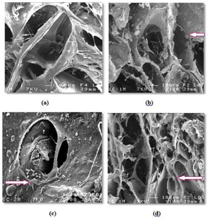
Generally, all prepared scaffolds' external and internal surfaces showed SE micrographs, exhibiting an open, highly porous microstructure with noticeable pore interconnectivity. All different scaffold compositions [C, 1C:1M, 1C:2M, and 2C:1M] exhibited a wide range of pore sizes that were observed within the same SE. Concerning the incorporated dispersed bioactive glass [M], it was significantly noted that an increase in the proportion of M yielded scaffolds with consequently smaller pore sizes and decreasing percentage of porosity (Fig. 9a-9d).
3.1.4. Porosity Measurement
Using the mercury intrusion pore sizer, the average pore diameter [4V/A] for the elaborated four scaffold compositions [C, 1C:1M, 1C:2M and 2C:1M] was 0.0698 µm, 0.0954 µm, 0.0923µm and 0.0849 µm, respectively.
3.1.4.1. Apparent [Skeletal] Density [g/ml]
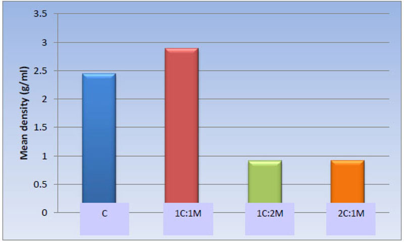
Statistically, the one-way ANOVA test revealed a significant difference among the groups [P-value < 0.001]. Also, pair-wise comparisons among scaffold compositions showed no statistically significant difference between C [2.45 ± 0.62 g/ml] and 1C:1M [2.89 ± 0.35 g/ml] scaffold, where both compositions showed the highest statistically significant mean values. There was no statistically significant difference between 1C:2M [0.91 ± 0.12 g/ml] and 2C:1M [0.92 ± 0.09 g/ml], as both revealed least statistically significant mean values (Table 4, Fig. 10).
| Scaffold | C | 1C:1M | 1C:2M | 2C:1M | P-value |
|---|---|---|---|---|---|
| Mean ± SD [g/ml] |
2.45 ± 0.62 a | 2.89 ± 0.35 a | 0.91 ± 0.12 b | 0.92 ± 0.09 b | <0.001* |
3.1.4.2. Bulk Density
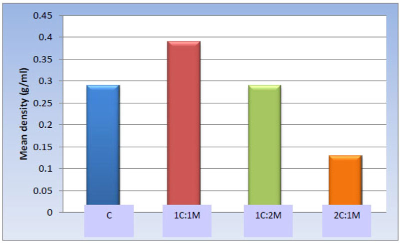
One-way ANOVA test revealed statistically significant differences among the groups [P-value < 0.001]. Afterward, pair-wise comparisons among the scaffold compositions showed that 1C:1M scaffold exhibited the statistically significantly highest mean value [g/ml] [0.39 ± 0.06 g/ml]. Evidently, no significant statistical difference was detected between C and 1C:2M scaffold [0.29 ± 0.08 and 0.29 ± 0.09 g/ml, respectively]; both showed statistically significantly lower mean values. 2C:1M scaffold showed the least statistically significant scaffold mean value [0.13 ± 0.03 g/ml] (Table 5, Fig. 11).
| Scaffold | C | 1C:1M | 1C:2M | 2C:1M | P-value |
|---|---|---|---|---|---|
| Mean ± SD [g/ml] |
0.29 ± 0.08 b | 0.39 ± 0.06 a | 0.29 ± 0.09 b | 0.13 ± 0.03 c | <0.001* |
3.1.4.3. Porosity Percentage
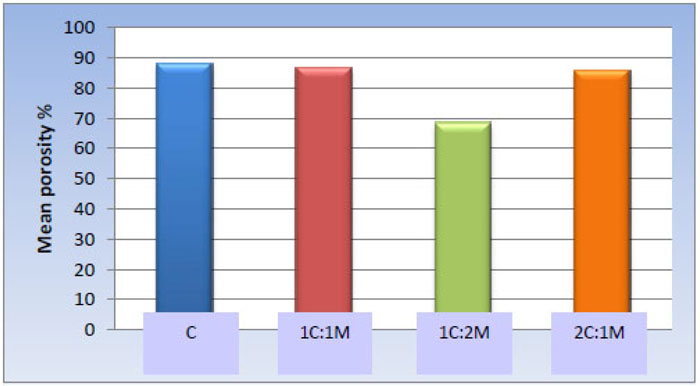
One-way ANOVA test revealed statistically significant differences among the scaffold groups [P-value < 0.001]. Furthermore, pair-wise comparisons among the scaffold compositions showed no significant statistical difference among C, 1C:1M, and 2C:1M scaffolds [88.12 ± 5.12%, 86.65 ± 7.24%, and 85.91 ± 10.18% respectively]; all revealed statistically significantly highest mean values. The 1C:2M scaffold showed the least mean porosity percentage [68.62 ± 8.52%] (Table 6, Fig. 12).
| Scaffold | C | 1C:1M | 1C:2M | 2C:1M | P-value |
|---|---|---|---|---|---|
| Mean ± SD Porosity % |
88.12 ± 5.12 a | 86.65 ± 7.24 a | 68.62 ± 8.52 b | 85.91 ± 10.18 a | <0.001* |
3.1.5. Compressive Strength Assessment
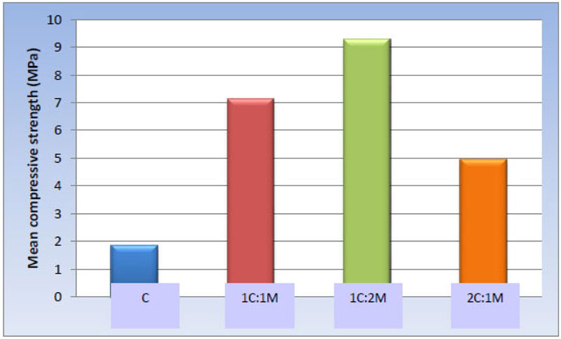
One-way ANOVA test revealed statistically significant differences among the scaffold groups [P-value < 0.001. Moreover, pair-wise comparisons between the scaffold compositions showed that 1C:2M scaffolds presented the statistically significantly highest mean compressive strength [9.30 ± 1.45 MPa], while 1C:1M scaffolds showed statistically significantly lower mean value [7.15 ± 1.05 MPa]. 2C:1M scaffolds showed substantially lower mean compressive strength [4.94 ± 0.59 MPa], and C scaffolds had the statistically significantly most insufficient mean compressive strength [1.87 ± 0.44 MPa] (Table 7, Fig. 13).
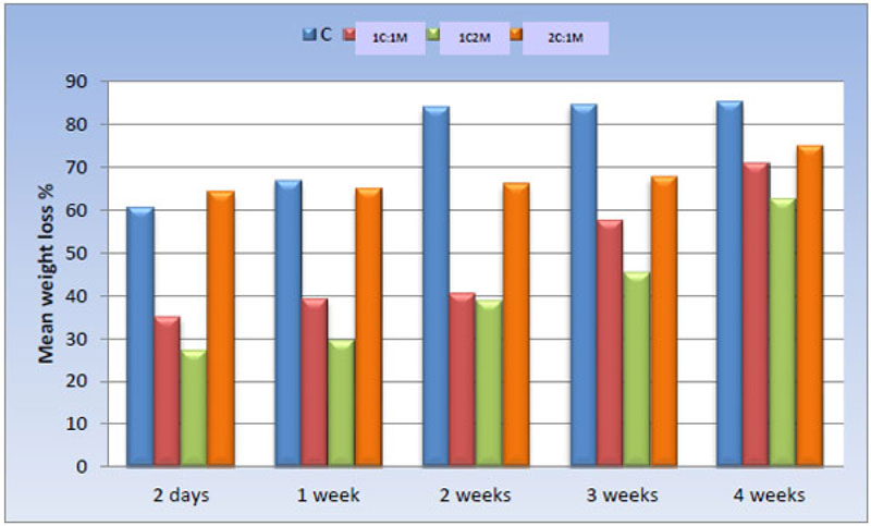
3.1.6. Ex-vivo Biodegradation in SBF
The weight loss percentage of all scaffold compositions immersed in SBF was calculated and statistically analyzed over time using a One-way ANOVA test and Pair-wise comparisons between them (Fig. 14).
| Scaffold | C | 1C:1M | 1C:2M | 2C:1M | P-value |
|---|---|---|---|---|---|
| Mean ± SD [MPa] |
1.87 ± 0.44 d | 7.15 ± 1.05 b | 9.30 ± 1.45 a | 4.94 ± 0.59 c | <0.001* |
4. DISCUSSION
In the study, natural chitosan of high DDA [degree of deacetylation] and medium viscosity was selected, aiming to achieve complete homogenous solubility of its powder and to promote mesenchymal cell adhesion on the designed chitosan scaffold structures, in agreement with Bhattarai et al. [33]. The chitosan DDA that is adjusted in the manufacturer controls the percentage of amine molecules in chitosan polymer chains. Consequently, DDA modifies the physico-chemical charac- teristics [i.e., crystallinity, solubility, and swelling behavior] and biological properties [osteogenic enhancement] of the obtained chitosan polymer [9, 11]. Duarte et al. [2012] [34] reported that the density of those positive amine charges [NH3+] on the chitosan chain was directly proportional to the DDA. In addition, Kim et al. [2011] [35] reported that the degradation kinetics of the polycationic chitosan polymer seemed to be inversely related to its DDA.
The prepared biocomposite scaffolds were fabricated from chitosan polymer matrix and 46S6 glass [M] [i.e., SiO2 glasses containing Ca and P] in order to achieve successful bone tissue regeneration [36].The scaffolds were prepared by combined bioactivity of both chitosan and 46S6 glass to lead to improvement in the mechanical properties [i.e., compressive strength] of the prepared scaffolds in order to enable them to withstand load application in stress-bearing areas of bone [37]. When contacted with a physiological SBF solution, the mechanism of glass bioactivity and bone adhesion process was attributed to the developed and precipitated carbonate substituted hydroxyapatite-like “HCA” layer upon the bioactive glass surface [Jones, 2013] [36]. Fortunately, that HCA layer [Ca/P ratio ~ 1.66] was found to be too similar to the mineral constituents of human bones, therefore, attaching firmly with vital tissues [38]. However, specific details about the chemical and structural changes of that HCA layer were still unclear; it is generally interpreted to inaugurate as a product of sequential biochemical reactions on the surface of the implanted bioactive glass [21, 36].
Obtained study results show that the 1C:2M scaffold compositions revealed the highest viscosity of all prepared scaffold consistencies, as it relatively incorporated optimum proportion of high-density M of all manufactured composite TE scaffolds. Comparing the elaborated scaffolds in SE micrograph, 1C:2M scaffolds showed the most abundant spindles of apatite formation, which might be due to the incorporation of NaOH solution and distilled water into its interconnected porous structure during laboratory preparation. Moreover, the FTIR analysis has confirmed the bioactivity of that scaffold composition, as the thickness of the developed apatite layer was increasing with the time of immersion in SBF. Those obtained promising results were found to be in agreement with Jones [2013] [36], who stated that osteogenesis was strongly correlated to the reaction of dissolution products of bioactive glasses on human osteoprogenitor cells that stimulated bone regeneration.
The freeze-drying technique [or thermally induced phase separation “TIPS”] was used to obtain a porous dry scaffold. The freezing stage involved a polymer-rich phase [i.e., with a higher polymer concentration], however, a polymer-lean phase [i.e., with a lower polymer concentration] was obtained following the drying stage under vacuum. That polymer phase directly evaporated into a gaseous state by sublimation, and consequently, it produced a homogenously interconnected microporous structure [39, 40].
Fortunately, IR spectra of all C/M biocomposite scaffold compositions showed the characteristic bands for C and M (Fig. 8), where many distinctive IR bands were shifted, distorted, or had disappeared, which might be attributed to specific chemical interactions between M and C. Thus, those IR illustrated that the functional groups of the bands had participated in bonding with M, which was in agreement with Mota et al. [2012] [41] and Jones [2013] [36] who stated that the developed HCA layer created a distinct surface favorable for osteogenic cell adhesion and appropriate proliferation.
Based on the results of established physicochemical characterization for all C/M compositions [42-44], the fabricated 1C:2M biocomposite scaffold was eluted as the optimum scaffold composition designed for osteogenesis [proper biocompatibility, bioactivity, porosity, biodegradation, compressive strength] and acting as a drug delivery device [45-48].
CONCLUSION
The following points can be concluded from the study: fabrication of the bioactive composite scaffold structure for bone TE seems successful. The addition of the elaborated bioactive glass to the prepared chitosan-based scaffold has improved not only the in vitro bioactivity but has also increased the compressive strength of the biocomposite scaffolds. Also, the composite scaffold materials were observed to have a controlled rate of biodegradation. The chemical composition and proportion of ingredients in TE scaffolds seem critical for their properties and clinical applications. Incorporating the bioactive glass within the selected medium viscosity chitosan with proper implementation of the freeze-drying technique has produced promising TE scaffold structures.
Characterization of the fabricated promising bioactive composite scaffolds appears to coincide with the essential requirements of bone TE scaffolds, such as microstructure [pore size, percentage, distribution, and interconnectivity], ex-vivo bioactivity, mechanical properties, and biodegradability. The constructed bioactive composite scaffolds are recommended for further experimental research for bone TE and when the results obtained are hopeful, the clinical trials can be attempted.
ETHICS APPROVAL AND CONSENT TO PARTICIPATE
Not applicable.
HUMAN AND ANIMAL RIGHTS
All the experimental procedures were carried out under international guidelines for the care and use of laboratory animals.
CONSENT FOR PUBLICATION
Not applicable.
AVAILABILITY OF DATA AND MATERIALS
Not applicable.
FUNDING
None.
CONFLICT OF INTEREST
The author declares no conflict of interest, financial or otherwise.
ACKNOWLEDGEMENTS
Not applicable.

