All published articles of this journal are available on ScienceDirect.

An Optical System to Monitor the Displacement Field of Glass-fibre Posts Subjected to Thermal Loading
Authors Info & Affiliations
Abstract
Endocanalar posts are necessary to build up and retain coronal restorations but they do not reinforce dental roots. It was observed that the dislodgement of post-retained restorations commonly occurs after several years of function and long-term retention may be influenced by various factors such as temperature changes. Temperature changes, in fact, produce micrometric deformations of post and surrounding tissues/materials that may generate high stress concentrations at the interface thus leading to failure.
In this study we present an optical system based on the projection moiré technique that has been utilized to monitor the displacement field of endocanalar glass-fibre posts subjected to temperature changes.
Measurements were performed on forty samples and the average displacement values registered at the apical and middle region were determined for six different temperature levels. A total of 480 displacement measurements was hence performed.
The values of the standard deviation computed for each of the tested temperatures over the forty samples appear reasonably small which proves the robustness and the reliability of the proposed optical technique. The possible implications for the use of the system in the applicative context were discussed.
INTRODUCTION
Endodontically-treated teeth may run a higher risk of failure than vital teeth [1, 2]. Although posts are necessary to retain coronal build-up materials, they do not reinforce roots and may even weaken them through loss of radicular dentin necessitated by post-space preparation [3-5]. Some authors asserted that posts may interfere with the mechanical resistance of treated teeth thus leading to an increased risk of damage for residual tooth structure [6-10].
Some studies have reported that fiber-reinforced resin posts provide lower retention in comparison with metal posts [11, 12]. Conversely, other studies reported no significant differences between the retention of fiber-reinforced resin and metal posts [13, 14]. Among the fiber-reinforced resin posts, glass-fiber posts play a role of predominant importance. They are composed of glass fibers, inorganic filler and a resin matrix and are usually luted with a resin cement to increase their retention and improve the mechanical performance of the restored teeth [15, 16]. Investigations on the effects of different combinations of irrigants and sealers on the shear bond strength at the post-dentine interface have been previously carried out [17, 18]. Finite element models reproducing the structural response of endodontically treated teeth were also developed [19, 20]. From the clinical point of view, it was observed that the dislodgement of post-retained restorations commonly occurs after several years of function, and long-term retention may be influenced by various factors such as temperature changes and dynamic mechanical loading [9, 21-23]. In particular, temperature changes produce micrometric deformations of post and adjacent tissues/materials (ATM). When thermal properties of the latter ones significantly differ from those of post, temperature changes may originate high stresses at the post/ATM interface that can lead to failure.
Generally speaking, the interfaces between materials with different physical properties such as the thermal properties, represent areas of weakness as local discrepancies influence stress-strain distribution [8]. A number of studies are available in the literature where the thermal properties of different dental materials are reported [24]. Some of them focused on the measurement of the thermal expansion coefficient [25-27], others on thermal conductivity [24, 28, 29], others on thermal diffusivity [29-31] etc. In general, the interaction between two bodies put in contact and subjected to thermal loading is the result of complex phenomena that depend not only on the specific values of the thermal properties but also on the way the thermal properties interact one each other both in stationary and transient conditions. Developing a theoretical model capable of reproducing the structural response of bodies put in contact and subjected to thermal loading is a very difficult task. The models currently available in the literature refer to simplified conditions and geometries that are very far from those actually occurring in the practice. In such a context, an experimental technique capable of monitoring the displacement field produced by a thermal load is of paramount importance not only to assess the structural behavior of the system but also to identify all the possible dental materials that can be put in contact and utilized to fabricate interfaces that, in the presence of thermal loadings, do not undergo to large stress values.
In this article we present an optical system based on the projection moiré technique that allows the displacement field of endocanalar glass-fibre posts subjected to thermal loading to be reconstructed with high accuracy. Projection moiré, the basic optical technique previously utilized with success to contour the shape of objects [32, 33] as well as to analyze the displacement field of industrial components under different boundary and loading conditions [34-37] was properly implemented in an ad hoc designed optical set-up aimed at monitoring the displacements of endocanalar posts subjected to temperature changes. The displacement of forty samples was measured. The rather low values of standard deviation prove the reliability of the proposed experimental technique. The possible implications for the use of the system in the applicative context were discussed.
MATERIALS AND METHODS
Experimental Set-up
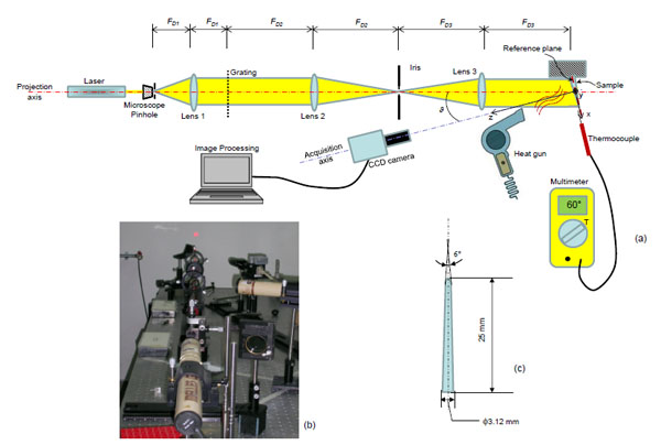
The optical set-up utilized in the study is articulated in two principal branches: the first one includes different optical components and is devoted to the projection of structured, collimated and coherent light onto the sample surface; the second one includes only a CCD camera and is devoted to the acquisition of the projected patterns of lines. All the components of the projection branch, i.e. the laser source, the microscope/pinhole system, the lens 1, the grating, the lens 2, the iris and the lens 3, are aligned with the projection axis (highlighted in red, (Fig. 1) while the optical axis of the CCD camera, that is the only component of the acquisition branch, is aligned with the acquisition axis (highlighted in blue, (Fig. 1). CCD camera is equipped with a long working distance objective. The angle ϑ made by the projection axis and the acquisition axis utilized in the study was 20°. The laser source (35 mW, He-Ne, Melles-Griot, Rochester, NY, USA) generates a coherent and polarized light beam that goes through the microscope/pinhole system. The microscope expands the beam while the pinhole removes all the noise effects of the parasitic diffraction phenomena produced during the expansion. The exit pupil of the pinhole is located at the focal distance FD1 = 200 mm of the lens 1; with this arrangement, the spherical wave-fronts impinging the lens are converted into planar wave-fronts and hence the light beam coming out from the lens is collimated. This beam first passes through a Ronchi ruling with a pitch of p0=84.67 µm and then through the lens 2 with a focal distance FD2 = 300 mm (Fig. 1). In the focal plane of this lens, the Fourier transform of the light wave-front diffracted by the grating creates. By changing the aperture of the iris - located just in the focal plane of lens 2 -, to select the diffraction orders 0 and one of two orders ±1, a sinusoidal carrier can be produced with the projected grating pitch. The iris is located not only in the focal plane of lens 2 but also in that of lens 3 which is characterized by a focal distance FD3 = FD2 = 300 mm. Therefore, the light beam coming out from the iris is collimated by the lens 3 and the collimated wave front so created and carrying the filtered spectrum of the grating is finally projected onto the surface of the endocanalar post (Fig. 1). The patterns of lines projected on the sample surface are acquired by a CCD camera. By equipping the camera with a long working distance objective, the acquired field of view was as large as approximately the post length. A heat gun placed in front of the sample was utilized to blow hot air on the sample surface. A thermocouple located just in the vicinity of the post surface lapped from the hot air was utilized to monitor the sample temperature (Fig. 1).
In order to measure the sample displacement during the heating process, by means of the above described optical set-up, two procedures must be carried out: the calibration and the processing of the acquired images. It is worthy to note that the experimental set-up above described allows the sample geometry to be contoured, therefore the displacement field produced by the thermal loading will be calculated as the difference between the sample contour at a given temperature and that at the environment temperature.
Calibration Procedure and Processing of Images
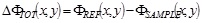
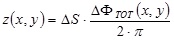
The calibration procedure requires to project patterns of lines - generated with the projection branch of the optical set-up described above - onto the surface of a reference plane (indicated in Fig. 1a) with a dashed red line) which is the plane with respect to which the depth of all the acquired points of the sample is measured. The acquired images of the projected lines are then processed to extract the phase map. To this purpose, the fast Fourier transform is first calculated, and hence, in the Fourier space, the frequency at which the maximum intensity of the power spectrum is identified. After implementing band-pass filters, the inverse Fourier transform is computed and from the obtained filtered image, through the in-quadrature method, the phase map ΦREF(x,y) is extracted. At this point, the reference plane can be removed and replaced by the sample. Again, the patterns of lines are projected onto the sample surface (Fig. 2a) and, adopting the same procedure described above, the filtered image (Fig. 2b) and the phase map (Fig. 2c) of the sample ΦSAMPLE(x,y) is extracted. The total phase ∆ΦTOT(x,y) can be hence computed as:
 |
(1) |
The height z(x,y) of each point of the sample with respect to the reference plane can be calculated as:
 |
(2) |
where the sensitivity ∆S is a quantity depending on the set-up geometry/arrangement and is given by ∆S = p0/sin ϑ. In the specific case, it is ∆S = 247.55 µm/fringe.
Experiments
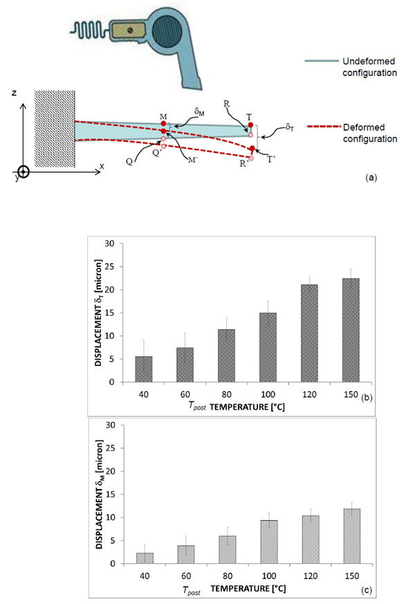
Forty samples, 25 mm long with a 6° conicity angle (Surgi post Multi Conical, Miromed s.r.l., Lainate (MI), Italy), were tested. The samples are shaped as a frustum of cone, the larger base having a diameter of 3.12 mm, the smaller one of 0.5 mm (Fig. 1c). By means of the optical set-up the post geometry was first acquired at environment temperature Tenv = 18 °C. Then, by using a heat gun placed in front of the sample, hot air was blown on the sample surface thus increasing its temperature. The increase of the temperature produces an inflection of the sample towards the side opposite to where the heat gun is located (Fig. 3a). The post geometry was hence contoured, - i.e. the coordinate z(x,y) (with respect to the reference plane) of each point of the post surface was determined, - at the following six temperatures Tpost: 40, 60, 80, 100, 120 and 150 °C. The acquisition was done as soon as the thermocouple measured the above mentioned temperatures Tpost. Between two consecutive acquisitions, a 10-minute time interval was waited so that the sample temperature, at the beginning of the new acquisition, is equal to Tenv. In order to make sure that no residual deformations were left by thermal loading in the currently tested post, a new image of the post was recorded after the 10-minute temperature recovery interval. This image was digitally superimposed on the reference image of the same post and the corresponding pattern thus generated was carefully analyzed. Since no moiré fringes were seen to form, we concluded that in the present experiments there was never residual deformation between two consecutive measurements performed on the same post.
Let M and T be two physical points, placed in the middle and tip section of the sample surface before blowing hot air and M’ and T’ the same points after the temperature reaches the value Tpost (Fig. 3a). If z(xM,yM)Tpost and z(xT,yT)Tpost are the heights of the post in correspondence of the points M and T, respectively, at the temperature Tpost, and z(xM,yM)Tenv and z(xT,yT)Tenv are the heights of the same points at the environment temperature Tenv, the displacements δM and δT experienced by these two points at the temperature Tpost can be computed as:
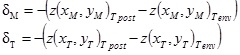 |
(3) |
For each of the six hypothesized values of Tpost, the displacements δM and δT averaged over the forty samples and the standard deviations were computed. A total of 2 (number of points (M and T) where the displacement was measured) × 6 (number of considered temperature levels) × 40 (number of tested samples) = 480 measurements were carried out.
RESULTS AND DISCUSSION
Increasing values of the (average) displacement δM and δT were measured for increasing levels of temperature Tpost (Fig. 3b, c). In particular, for a fixed temperature, δT is always greater than δM. This is consistent with the physics of the problem. The conical post behaves as a cantilever beam clamped on the larger base, therefore any inflection (that produces the rotation of the sample sections) of the sample leads to increasing displacement values as we move from the base towards the post tip. The sign of the measured displacement is also consistent with our expectations. In fact, the hot air blown by the heat gun produces a non-uniform temperature field where the temperature of the post fibres decreases as we move from the fibres closer to the heat gun (e.g. the fibre including the points M and T, Fig. (3a) towards those more far (e.g. the fibre including the points Q and R, (Fig. 3a). Therefore, the fibres closer to the heat gun will experience a larger elongation compared to those more far and this leads the post to inflect on the side opposite to where the heat gun is located. A displacement with a sign opposite to that found in the experiments would mean, obviously, that the inflection takes place in the side opposite to the one shown in Fig. (3a).
The proposed technique presents some limitations. First of all, the processing of the acquired images is not automatic and the user has to make a number of choices such as the shape and the dimension of the band pass filter to be implemented in the Fourier space. A possible strategy that can be adopted to overcome this limitation consists in performing a large number of experiments on a wide variety of posts (or other dental materials) and finding, for each tested material, the optimal processing parameters; therefore, these parameters can be implemented in ad hoc routine that automatically executes the processing of the acquired images hence limiting the user intervention. Second, the technique requires a thorough and time-expensive calibration process that can take two to five hours. However, once the calibration process was terminated, the set-up can be utilized for measuring the displacement of a large number of samples. For example, to measure the displacements of all the forty samples analyzed in this study, calibration was done once and for all.
In spite of these limitations, as stated above, the displacement values measured with the proposed system are consistent with the physics of the problem and with our expectations. Furthermore, the values of the standard deviation computed, for each of the tested temperature Tpost, over the forty tested samples appear reasonably small thus indicating the rather good reliability of the proposed optical technique. These values of standard deviation can certainly be explained with: (i) the differences intrinsically present in the resin matrix or in the glass fiber orientation of the different tested samples; (ii) the positioning errors committed every time a sample was removed and replaced by another one. As demonstrated in a previous study [36] the projection moiré technique has the potentiality of providing results with an accuracy of the order of 1/500 of the sensitivity ∆S of the system which means, in this case, about half a micron. Furthermore, the technique appears very suited to monitor the displacement field in a wide range of dimensions that goes from some microns [36, 37] to meters [32, 38].
It is worthy to note that the issue of identifying the possible materials that can be utilized to fabricate interfaces subjected to temperature changes cannot be addressed by simply determining the thermal expansion coefficient [29]. As stated above, the stress state that creates at the interface depends on different thermal properties as well as on the way they interact mutually. A possible application of the proposed optical set-up consists in implementing it on different samples, all shaped with a specific geometry, made from different dental materials and in comparing the resulting displacement fields. Those materials that exhibit comparable displacement values can be put in contact and utilized to fabricate interfaces. Any possible variation of the temperature field, in fact, will produce similar displacement fields in the two materials thus generating negligible thermal stress values.
Another important advantage of the proposed optical system is that the monitoring of the displacement field occurs via a CCD camera which can acquire images with high frequency. This can be properly exploited to describe and evaluate the displacement field and, hence, the stress state, not only in the stationary but also in the transient conditions.
CONCLUSION
We presented an optical system that has been utilized to determine the displacement field in endocanalar glass-fibre posts subjected to temperature changes. Measurements were performed on forty samples and the average displacement values registered at the apical and middle regions of the post were determined for six different temperature levels. The rather small values of standard deviation that can be justified with arguments independent of the optical system are a proof of the good reliability of the proposed optical technique. The proposed technique can be utilized to identify all the dental materials that can be utilized to fabricate interfaces subjected to thermal loading.
CONFLICT OF INTEREST
The authors confirm that this article content has no conflict of interest.
ACKNOWLEDGEMENTS
Declared none.