All published articles of this journal are available on ScienceDirect.

Impact of Dynamic Loading on the Implant-abutment Interface Using a Gas-enhanced Permeation Test In Vitro
Authors Info & Affiliations
Abstract
Purpose : To assess implant leakage under static conditions as well as during and after dynamic loading. Materials and methods : Implants (Astra Tech (A), Biomet 3i (B) and Nobel Biocare (C)) were evaluated for leakage (n=8/group). Testing to assess the gas pressure change over time (hPa/min) and infiltrated fluid volume, was performed in a Gas Enhanced Permeation Test (GEPT) to qualify embedding. Implant apexes were then drilled, abutments were mounted and resin build-ups were fabricated. GEPT was reassessed. Samples were afterward mounted in a computer-controlled masticator while tested to bacterial leakage, they were daily observed for turbidity. Samples were then reassessed using GEPT. Dunnett's and Fisher's exact tests were utilized to compare implant and to analyze bacterial leakage. Results : Significant differences in GEPT values were shown after loading (p=0.034). Leakage resistance was best for B when compared to C (p=0.023). Samples with higher GEPT values demonstrated earlier bacterial leakage, occurring after 1 or 2 days (A=4, B=0, C=6) and showing favorability for implant system B (p=0.009). Conclusion : Implants leaking under static conditions had increased potential for bacterial leakage under dynamic conditions. As strongly correlating to sophisticated analytical methods, GEPT is a promising technique for assessing the overall implant system leakage resistance.
1. INTRODUCTION
Significant emphasis has been placed on the research and development of implant-abutment interfaces, as well as the corresponding test methods because of the potential for bacterial harborage within the implant should this interface leak. Due to its - in most cases - submucosal location and configuration, the implant-abutment interface is difficult to clean or disinfect and may be regarded as a potent source for continuous infection [1], which may lead to mucositis and even peri-implantitis [2, 3]. Even implant failure was correlated to this bacterial inhabitation [4].
Several models have been employed to test implants for the implant-abutment interface integrity and numerous designs have been proposed by manufacturers to increase and enhance its tightness: Molecular, bacterial and fluid penetration, were the most investigated models under static conditions for testing implants leakage. A recent study [5] showed a high correlation between bacterial leakage and fluid permeation utilizing a gas-enhanced permeation test (GEPT) with a high sensitivity for fluid permeation in detecting leakage in implants.
Other studies investigated leakage under dynamic conditions, as it is more relevant to the clinical situation [6, 7]. It was suggested that implant systems are more susceptible to leakage under dynamic conditions due to the so-called pumping effect [7]. Specific connection designs such as the taper lock were suspected to be tighter after dynamic loading due to the relative displacement over time at the implant abutment interface, which might reduce the assembly movements due to the theoretical gap reduction between the interfacial surfaces [7]. Based on this knowledge, it is more clinically relevant to study leakage under dynamic conditions as the implant-abutment assembly is experiencing different functional adaptations, which might lead to deterioration or perhaps even improvement of the implant abutment interface in terms of leakage. However, most studies concentrated on implant leakage during dynamic loading only regardless of the preloading status and quality of the Implant-abutment interface, mainly because de-assembling the abutment was required to reach and then sample the inner implant chamber [6]. A non-destructive protocol allowing for a correlation between static status and implant performance during and after dynamic conditions is still warranted. It is because existing protocols interfere with the integrity of implant-abutment interface due to the methods required to disruption of the implant-abutment interface and repeated screw tightening [8]. Ideally, the evaluation of implant leakage should therefore be performed under static and thermo-mechanical dynamic loading conditions in one set of identical implants without being re-assembled.
This study represents one of a series of studies, which aimed to analyse the leakage of different implant systems in vitro. Whereas a previous study assessed these implant systems only with regard to their leakage status under static conditions [5], this follow-up study aimed to test the same three implant system designs, but now under dynamic conditions with correlation to their static preloading status. It was hypothesized that a tight implant under static conditions would stay tight under loading conditions and vice versa. In addition, it was suggested that the implant design does influence the implant performance and stability under dynamic conditions.
2. MATERIALS AND METHODS
Three implant systems were selected (Table 1): one with a taper lock and internal hexagonal mating surface design (Astra Tech (A)). a second system with a flat-to-flat interface design and internal hexagonal mating surface (Biomet 3i (B)) and one system, with a flat-to-flat and a trilobe mating surface (Nobel Biocare (C)). For each system, eight implants were assigned for leakage testing. Two additional implants were used as negative controls without drilling a connection between the two chambers, thus serving to control the adequate embedding set-up. All implants were mounted and static GEPT values were assessed according to a previously published and validated protocol [5, 9].
Implants and specifications of parts used in the study.
| Group A | Group B | Group C | |
|---|---|---|---|
| Description |
Astra Tech™ OsseoSpeed™ TX/S 4.0x15 mm |
OSSEOTITE® Tapered Certain® PREVAIL® 4.0x15 mm |
Nobel Replace® Tapered Platform Switch 4.3x16 mm |
| Abutment | TiDesign 3.5/4.0-1.5 mm |
GingiHue® - 2 mm |
Esthetic Abutment NP - 3mm |
| Screw | Uncoated Screw | Gold Coated Gold-Tite® Screw |
Uncoated Screw |
Table 1: Parts used in each group assembly
Implants performance under static and dynamic loading conditions.
| Imp. No. |
Effective leakage (hPa/min) |
Water Volume before (ml) |
Time of Bac. Leakage (day) |
Influence on leakage After Dyn. Loading (hPa/min) |
Water Volume after (ml) |
|
|---|---|---|---|---|---|---|
| Group A | 1 | 0.004 | 0.000 | No leakage | -0.017 | 0.000 |
| 2 | 0.002 | 0.000 | No leakage | 0.001 | 0.000 | |
| 3 | 0.068 | 0.042 | No leakage | -0.066 | 0.000 | |
| 4 | 0.004 | 0.000 | No leakage | 0.003 | 0.000 | |
| 5 | 5.531 | 2.500 | 1 | -4.900 | 0.258 | |
| 6 | 5.53 | 2.500 | 1 | 0.000 | 2.500 | |
| 7 | 0.189 | 0.096 | 1 | -0.030 | 0.000 | |
| 8 | 5.503 | 2.500 | 1 | -5.325 | 0.089 | |
| *9 | 0.025 | 0.000 | No leakage | 0.002 | 0.000 | |
| *10 | 0.027 | 0.000 | No leakage | -0.002 | 0.000 | |
| Group B | 1 | 0.008 | 0.000 | No leakage | 0.010 | 0.000 |
| 2 | 0.009 | 0.000 | No leakage | 0.016 | 0.000 | |
| 3 | 0.026 | 0.000 | No leakage | 0.014 | 0.000 | |
| 4 | 0.008 | 0.000 | No leakage | 0.008 | 0.000 | |
| 5 | 0.020 | 0.000 | No leakage | 0.010 | 0.000 | |
| 6 | 0.014 | 0.000 | No leakage | 0.030 | 0.000 | |
| 7 | 0.004 | 0.000 | No leakage | -0.005 | 0.000 | |
| 8 | 0.008 | 0.000 | No leakage | -0.007 | 0.000 | |
| *9 | 0.002 | 0.000 | No leakage | 0.001 | 0.000 | |
| *10 | 0.016 | 0.000 | No leakage | -0.003 | 0.000 | |
| Group C | 1 | 0.048 | 0.036 | 1 | 5.463 | 2.500 |
| 2 | 0.007 | 0.000 | No leakage | 0.025 | 0.000 | |
| 3 | 0.338 | 0.161 | 2 | -0.300 | 0.000 | |
| 4 | 0.005 | 0.000 | 2 | 5.509 | 2.500 | |
| 5 | 5.531 | 2.500 | 1 | 0.000 | 2.500 | |
| 6 | 0.042 | 0.026 | No leakage | -0.018 | 0.000 | |
| 7 | 0.151 | 0.076 | 1 | 0.014 | 0.073 | |
| 8 | 2.500 | 1 | 0.000 | 2.500 | ||
| *9 | 0.013 | 0.000 | No leakage | -0.002 | 0.000 | |
| *10 | 0.001 | 0.000 | No leakage | -0.001 | 0.000 |
Table 2: Detailed implant test performance. * Implants served as negative controls
2.1. Mounting of the Implants
All implants were mounted in custom made PVC discs with a diameter of 15 mm and a thickness of 3 mm. First, a drill corresponding to the implant diameter but with a reduction of 0.2 mm, measured at a distance 1 mm from the implant-abutment interface, was made in corresponding discs utilizing a parallelometer. The respective diameters were 3.8 mm (A), 3.3 mm (B) and 4.0 mm (C). Implants were then mounted to allow for exposure of 1mm of the implant-abutment interface. To promote robust sealing at the implant-disc interface, the disc was sandblasted from its lower side (50 μm aluminum oxide, Benzer-Dental AG, Zurich, Switzerland) and further conditioned and sealed using a light cured nail build-up gel system (Sina, Shenzhen Cyber Technology Ltd, Mainland, China).
2.2. Gas-enhanced Permeation test (GEPT)
All implant systems were tested for their baseline leakage value to ensure that the mounting procedure was perfectly sealed. These baseline values were used later as a reference to calculate the absolute implant leakage value [5]. The whole sample was mounted with an O-ring, which was lubricated with silicon grease (Molykote 111 compound, DOW Corning GMBH, Germany) at the middle of a split chamber set-up, thereby forming two completely isolated chambers. The upper compartment contained 2.5 ml physiologic saline solution and was positively pressurized, while a negative pressure was applied to the lower compartment. A total effective pressure difference of 1030 hPa was created between the two chambers and the drop in pressure difference was monitored utilizing a pressure difference-measuring device (Testo 526, Testo AG, Lenzkirch, Germany) over 40 min at a rate of 1 measurement/sec. The slope of the pressure drop at two fixed points of testing (1200 sec and 2400 sec) was used to quantify the pressure difference drop for each test system:
The permeated fluid volume was calculated by collecting it from the lower chamber and weighing it to determine its volume in milliliters.
After this baseline reading, implants were mounted inverted in a parallelometer and a connection was created by drilling from the apical direction towards the internal fixture using a 1 mm hard metal drill at a speed of 1100 rpm while undergoing continuous water-cooling. The implants were assessed to ensure that the internal threads were not damaged. For the negative control, two implants received the same treatment but without penetrating into the internal thread compartment as to test for possible deleterious effects of drilling on the integrity of previously assessed embedding procedure.
Implants were then held in a straight Kelly hemostat (Hu-Friedy Mfg. Co., Chicago, USA) and the abutments were positioned and attached to the implant using the respective screws according to the manufacturer's instructions with the recommended torques (Group A 20 Ncm, Group B 20 Ncm and Group C 35 Ncm). The abutments were then sandblasted (50 μm aluminum oxide) while the platform was protected with a punched rubber matrice. The screw channel was filled with a Teflon strip (Pink Waterline PTFE Tape, Oatey, Cleveland, Ohio, USA) and was then pre-treated with Monobond Plus (ivoclar vivadent AG, Schaan, Liechtenstein). Afterwards, an adhesive material (Clearfil SE Protect, Kuraray America Inc., USA) was applied and a standardized composite build-up (6mm diameter and 10 mm height) (Luxa Core Automix, DMG, Hamburg, Germany) was fabricated, which extended to the abutment restoration finish line without interfering with the implant-abutment interface.
The implants were tested again as described above and the baseline slope was subtracted from the test slope after build-up to determine the absolute leakage slope under static conditions and again after the thermodynamic loading to assess the effect after loading. The saline flow was recorded again (Table 2).
A maximum value of 5.55 hPa/min was allotted for implants deemed incapable of withstanding the initial testing period, which represents the highest slope corresponding to 2.5 ml fluid penetration over the whole testing period.
2.3. Bacterial Testing Dynamic Model
The loading system consisted of two tightly separated chambers as with the prior experiment (Fig. 1). The lower chamber was based on two hard stainless steel parts designed to be interlocked with a screw system and holding the mounted implant sample in between two rubber washers (outer diameter 15mm, inner diameter 10mm and thickness 1mm), which were located on both sides of the mounting disc. The upper chamber was created by an elastic, semi-transparent PVC lever, which was tightened on the lower holder and on the opposing antagonistic side with O-rings. This design allowed for placement of bacterial broth containing a bacterial strain (in the lower chamber), which can change the color of a detection media by hydrolyzing a certain component resulting in turbidity and blackening of the broth in the visible compartment. Conceptually, the bacterial cells can only penetrate through the drilled hole at the apical tip of the implant to reach the implant-abutment interface and then travel to the upper compartment. The antagonist was designed so that it forms a 30 degree angled surface, thereby allowing for exertion a luxation effect on the abutment and simulating a more the clinically relevant situation. The antagonist also contained a drilled hole through which the detection media can be filled prior to being sealed with a rubber piece to form a sealed compartment.
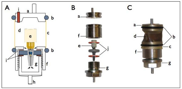
Schematic illustration of dynamic loading set up (A), photo of the different components prior to assembly (B) and fully assembled set-up (C). a. Antagonist, b. Tightening O-rings, c. Elastic semi-transparent lever, d. Upper compartment holding the indication medium, e. A mounted implant sample, f. Capping holder of lower chamber, g. Lower chamber compartment with screw third for tightening, h. Mounting holder for chewing machine cell, i. Indicating medium filling inlet, j. Sealing rubber washers.

Visual comparison of bacterial leaking vs. tight implant. (A) Tight implant and (B) leaking implant.
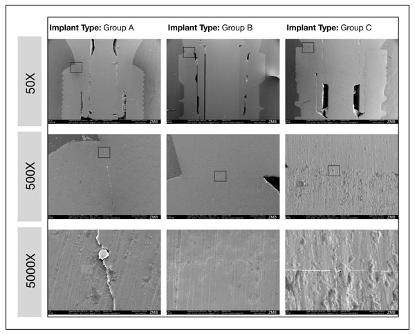
Representative samples of SEM images representing bacterially non-leaking samples with a GEPT score value of less than 0.090 hPa/min. The squared area determines the magnified section in each photo with higher magnification.
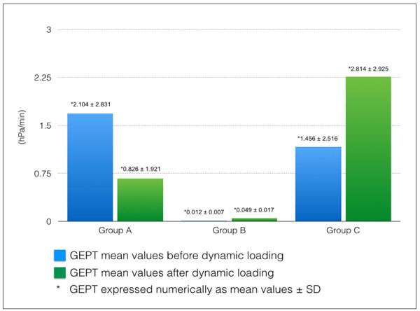
A graph showing a comparison of implants performance before and after dynamic loading presented as mean values ± SD.
2.4. Mounting the Samples for the Dynamic Loading
All samples and parts to be mounted into the test model were individually wrapped in autoclave sterilization bags. Gas sterilization took place utilizing ethylene oxide gas (3M AG, Rüschlikon, Switzerland) in a sterilizer (Sterivac 4XL, 3M AG, Rüschlikon, Switzerland) using the cold sterilization cycle at 37°C for 5,5 hours. All the packs were opened and the assemblies were then made under a clean bench (EVZ 120, SKAN AG, Basel, Switzerland). The lower chamber was initially filled with 1.5 ml of overnight culture of E. fecalis ATCC 29212 in fluid universal broth (FUM, Gmür and Gugenheim 1983). The culture was previously adjusted to 1.0 optical density at 550 nm. The implant and the two rubber washers were placed in position in the counterpart and were positioned on top. The two parts were then manually tightened together using pliers. The assembled part was held in a holder against the antagonist with a separating distance equivalent to the value established in the chewing chamber. The elastic semi-transparent lever taken out of finger Cots (PVC medium size, 0.35 mm thick, MUCAMBO – GUMMI Matthias Jacoby, Altrip, Germany) was mounted in position and tightened over the two sides with the O-rings (outer diameter 22 mm, inner diameter 18 mm, thickness 2mm; Fig. 1, C). After completion of this assembly, the upper chamber was filled with a 3 ml of enterococci-selective bile esculin azide broth (Enterococcosel Broth, Difco, Benton Dickinson Co..Sparks, MD, USA) to detect bacterial leakage by inspecting color change. The filling inlet was then sealed with a tight fitting cylindrical shaped rubber component (Fig. 1, i). The assemblies were mounted in the chewing machine and subjected to a computer-controlled mastication; 1'200'000 loadings under a stable water controlled temperature of 37°C. The samples were observed on a daily basis. Due to the slight change in the lever transparency, a light source (Laser class 3R, Intertronic, Interdiscount AG, Switzerland) was applied to improve detection. In the case of no leakage the light penetration through the clear medium resulted in a lamp glow appearance (Fig. 2, A). Whereas when leakage occurred, the pointed light source was reflected on the outer surface and could not penetrate through the darkened turbid medium (Fig. 2,B). At the end of the observation period, aseptic samples were obtained from both chambers (upper and lower) and cultured overnight in bloodagar plates (Colombia agar + 5% Sheep blood, bio Mérieux SA, Marcy l’Etoile, France) in an incubator (IL 115, INCU-Line, VWR, Dietikon, Switzerland) at 37°C to confirm the results and to ensure the involvement of a single bacteria type (i.e. no contamination and the survival in the lower stock chamber in all cases). To exclude any leakage after the thermo-mechanical challenge at the implant-disk interface, the drilled apices of all implants, which showed bacterial leakage under dynamic loading (A n=4 and B n= 6) were sealed again, i.e. they were sandblasted (50 μm aluminum oxide, Benzer-Dental AG, Zurich, Switzerland), further conditioned with Monobond Plus (ivoclar vivadent AG, Schaan, Liechtenstein), adhesivly treated (Clearfil SE Protect, Kuraray America Inc., USA) and closed with a resin build-up (Luxa Core Automix, DMG, Hamburg, Germany). GEPT was determined again given the hypotheses that the original leakage status (baseline) should be achieved again provided that the marginal mounting was still perfectly intact.
2.5. SEM Visual Assessment of Implants
Implant systems were assembled and then embedded in epoxy resin (Stycast 1266, Emerson & Cuming, Henkel Eleotronlo Materials, Westerlo, Belguim) and left to set for 24 hours. Afterward, they were sectioned into halves utilizing a slow speed diamond saw (0.4 mm, Strures GmbH, Zweigniederlassung, Switzerland). The hardened resin blocks were mounted in SEM carriers (SCD 030, Balzer Union AG, Balzer-FL) and gold sputtered (Oerlikon Balzers Coating AG, Balzer, Liechtenstein): Sections were coated with a 90 nm gold layer under 0.08 mbar and current of 45 mA over a period of 3 minutes. Implants were observed under SEM (Zeiss Supra V50, Carl Zeiss, Oberkochen, Germany) at magnifications 50X, 500X and 5000X (Fig. 3).
2.6. Statistical Analysis
GEPT performance data, mean values and standard deviations, were assessed prior to and following dynamic loading. An ANOVA was applied to test for significance between systems at each stage of testing. Additionally, a Dunnett post-hoc analysis was conducted to isolate the differences. While bacterial leakage was presented by means of days; exact test of Fisher was applied to compare between different implant systems.
3. RESULTS
Before dynamic loading the effective leakage of the three implant systems was (mean ± sd) 2.104 ± 2.831 for group A, 0.012 ± 0.007 for group B, and 1.456 ± 2.516 for group C. After dynamic loading the values were; group A 0.826 ± 1.921, group B 0.049 ± 0.017 and 2.814 ± 2.925 for group C (Fig. 4). An ANOVA resulted in an overall difference only after dynamic loading (p-value 0.034). A Dunnett post-hoc analysis with group C as a control group shows that the difference is mainly due to the significant lower average leakage value of group B compared to group C (p-value 0.023).
Bacterial leakage did not occur for any of group B implants, while 4 of the group A implants showed leakage after 1 day. Also, 4 of the group C implants showed early leakage after 1 day and 2 of the implants leaked after 2 days. The exact test of Fisher was applied to the corresponding 3 by 3 contingency table of leakage (no leakage, leakage after 1 day, leakage after 2 days) with the three-implant systems. The p-value was 0.009 in favor of group B.
4. DISCUSSION
The current study aimed to establish a protocol for testing implants under dynamic conditions using a validated gas-enhanced permeation testing method [5]. The protocol included the pre-evaluation of the implant seal status under static conditions before loading, which served as a baseline value. It was hypothesized that a tight implant under static conditions would also show a tight seal under dynamic conditions. This was corroborated by the findings of the present study where initially tight implants also showed a better sealing behavior under dynamic loading. Although no statistical significance could be found between different implant system designs before loading, there was a statistically significant difference observed after loading between group B and group C (p-value 0.034). The findings under static conditions are in contrast to a previous study, which showed significant differences between the groups [5]. However, the trends obtained in the present study are the same and the fact that no statistical difference could be found is attributable to the lower sample size of the present study, where only 8 implants were used as compared to 16 samples for each group in the previous study. Previous studies showed varying results regarding bacterial leakage under static conditions which ranged from 20-80% for internal hex and 20-60% for taper lock designs [10, 11]. These considerable variations may be related to the differences in study designs. However, once again during the dynamic loading, group C exhibited the highest number of leaking implants, followed by group A (6 and 4 of test implants respectively), while group B showed no leakage. The taper lock design (group A) was the only design which showed some improvement in tightness after dynamic loading (Fig. 4), but this was not statistically significant. This finding indirectly correlates to a previous study assessing tapered lock implants under dynamic loading, where an increase in the loosening torque after loading was observed [6]. On the other hand, group C, showed an overall increase in leakage as compared to the equivalent flat-to-flat design in group B. The difference in tightness corresponds to the difference in mating surface design. A finite element method to study micro-motions at the implant-abutment interface at different mating surfaces [12] showed higher micro-motions at the polygonal region in a trilobe design as compared to the micro-motion in a internal hexagonal design. The authors suggested that this fact might therefore lead to more bacterial penetration, which was actually corroborated by the findings of the current investigation.
In the present study, gap analysis was not quantitatively performed, but was used to visualize the situation of implants which showed GEPT values close to the a value of 0.09 hPa/min, which was arbitrarily defined in our previous study to be the cut-off value below which no bacterial leakage occurs [5]. The SEM confirmed the presence of small gaps only and thus the high sensitivity of GEPT measurements in detecting implant leakage over bacterial leakage. If spatial analysis is to be conducted, we suggest 3D analysis as a valuable tool to assess this attribute. The current model set-up was the first study in which the non-loaded performance of an implant system was correlated to its performance under dynamic loading conditions. It provided a continuous analysis of implants testing before, during and after dynamic loading. The bacterial leakage model (turbidity detection), per se, has a long history of use in leakage evaluation for both conventional dentistry [13] and implant dentistry [14, 15]. To our knowledge, it is the first time that it was applied in a dynamic model. The ideal model in which bacterial leakage can be directly detected during dynamic loading was challenging. It required replicating the conditions of an isolating split chamber system design, but which also allows direct detection of turbidity through a clear or semi-clear wall on the detection medium side and finally, has an elastic wall which does not interfere with the dynamic loading process. Cell cultures were taken to ensure leakage related to the used bacteria only and to confirm exclusion of any external contamination. In addition, it also proved that the bacteria could survive the whole testing period. Furthermore, the mounting quality after all experimental steps was re-tested: Theoretically, the difference between the GEPT at baseline and at the end of all experiment after re-sealing the implant apices should be zero. Indeed, we found very small differences only ranging from -0.010 to +0.009 hPa/min, which reflects an intact mounting and sealing quality at all times.
Implants failure due to the prosthetic assembly fixed on top depends on the following considerations: Mechanical factors, related to the load applied [16], the abutment retention type (cemented vs. screw retained) [17], and prosthesis retention (cemented vs. screw retained) [18]. The second important factor is the bacterial inhabitation in uncleansable niches [19].
Clearly, studies found that implant failure was correlated to the presence of gaps and their size at the implant-abutment interface [20-22]. Leakage provides an indirect indication of gaps present at the implant-abutment interface and can therefore be considered as a quantitative parameter to assess the quality of the connection at the implant-abutment interface [23]. The long-term survival of implants has been linked to the precision of the overall assembly of dental implant parts and thus the preservation of the surrounding supporting bone level [24, 25]. Nakazato and co-workers 1989 [26] have elaborated bacterial colonization at the prosthetic connector 4 hours after exposure to the oral environment, whereby gaps allowed fluid and bacteria shifts through the implant-abutment interface in both directions. Thus, the presence of gaps at the implant-abutment interface presents a risk factor which jeopardizes the prognosis of an implant [27]. Histological studies highlighting the importance of gap levels in relation to the bone crest demonstrated that the closer the gap was to the bone crest, the higher the risk of peri-implantitis [27, 28]. Quirynen and co-workers 2002 showed that persistent bacterial inoculation of the implant-abutment interface is related to a chronic inflammatory response at the bone crest.
CONCLUSION
This study elaborated a methodology to investigate the leakage of implant systems under static conditions which highly correlated to implants performance under dynamic loading. Implants with a flat-to-flat interface and internal hexagonal mating surfaces showed the best performance with regard to leakage under both static and dynamic conditions. This study has also provided a proof that tight implants under static conditions will provide better sealing characteristics under dynamic conditions, which in turn highlights the importance and relevance of in-vitro implant system leakage testing under static conditions, as a preclinical assessment parameter. It can also be concluded that the design of the implant-abutment interface and its stability plays a determinant role against bacterial leakage under dynamic loading.
CONFLICT OF INTEREST
The study design was conceived and executed independently, however the corresponding author PhD fellowship is supported – in part - by Biomet 3i.
ACKNOWLEDGEMENTS
Implant systems were obtained directly from each manufacturer utilizing funding through a research grant by Biomet 3i.