All published articles of this journal are available on ScienceDirect.

Stress Distribution of Hybrid Ceramic Implant-supported Superstructure Versus Zirconia and Lithium Disilicate Superstructures
Authors Info & Affiliations
Abstract
Introduction
The choice of crown material for dental implants is critical, and polymer-infiltrated hybrid ceramics have been proposed to mitigate excessive stress. However, research on the stress distribution in these materials and their impact on supporting structures is limited. This study evaluated stress distribution across various CAD/CAM crown materials: multilayered zirconia, polymer-infiltrated hybrid ceramics, and lithium disilicate ceramics on maxillary premolar implants.
Materials and Methods
A three-dimensional finite-element model simulating a maxillary premolar implant was developed, featuring a 3.7 mm diameter, 13 mm length, and 5.5 mm abutment height, and was covered with a 50 μm cement layer. The model was subjected to compressive vertical and oblique loads, and three superstructure materials were tested.
Results
The study noted slight differences in deformation and stress distribution among materials under the same load conditions. Multilayered zirconia crowns exhibited the least deformation, followed by lithium disilicate crowns, whereas polymer-infiltrated hybrid ceramics showed the most significant deformation.
Discussion
The polymer-infiltrated hybrid ceramics exhibited higher susceptibility to deformation due to their resin content. Resilient materials reduce implant stress; implant failure is unlikely at von Mises stress levels below 550 MPa. Oblique loading intensified stress and deformation across all structures, corroborating previous findings about risks to prosthetic parts and surrounding tissues. While cortical bone experienced higher stress than spongy bone, it did not exceed strength limits, particularly at the implant-abutment neck.
Conclusion
Stress and deformation increased progressively across all materials, with oblique loads producing greater stress than vertical loads. The bone and mucosa showed minimal response to the crown materials.
1. INTRODUCTION
Implant-supported prostheses have become a popular treatment option in dentistry, serving as an alternative to conventional Fixed Dental Prostheses (FDPs) due to their long-term clinical success rates and proven functional, biological, and mechanical advantages [1]. A lack of periodontal ligament around the implant may lead to direct transmission of occlusal stresses to the implant and the surrounding bone. The choice of prosthetic material is determined by its capacity to withstand masticatory forces and its aesthetic results [2]. Metal-ceramic restorations have been regarded as the gold standard in the prosthetic field for several decades due to their cost-effectiveness, established structural performance, and versatility. To achieve effective implant-supported restorations, selecting the appropriate superstructure is vital [3]. Implant superstructures can be manufactured from a multitude of materials, including Lithium Disilicate ceramic “LD”, which provides good marginal adaptation, high aesthetics, large fracture load, excellent bonding ability, and biocompatibility, resulting in substantial clinical success in posterior implant-supported restorations [4-6]. Nonetheless, these materials exhibit only moderate toughness (2 to 2.5 MPa.m1/2) as well as strength (400 to 600 MPa) when compared to zirconia restorations, which demonstrate toughness values between 3.5 and 4.5 MPa.m1/2 as well as strength values ranging from 800 to 1200 MPa [7].
Currently, highly translucent multilayered zirconia “MZ” is utilized in both implant-supported and tooth-supported restorations as a superstructure material, particularly in the esthetic zone. It integrates superior biocompatibility and mechanical properties with an aesthetically pleasing appearance. It also provides elevated fracture toughness and flexural strength, while the multilayered and translucency features effectively replicate natural tooth shade gradient properties [8-10]. Nevertheless, these rigid ceramics may lead to temporomandibular disorders and an excessively hard occlusal contact [11].
The growing adoption of computer-aided manufacturing (CAD-CAM) and computer-aided design systems has led to the fabrication of various materials for chair-side milling, including resin-matrix ceramics [12], which comprise an organic matrix and a significant ceramic component [13]. At present, various types of resin matrix ceramics exist, such as polymer-infiltrated hybrid ceramics “PHC” (e.g., Vita Enamic), as well as resin nano-ceramics. It exhibits resistance to fracture and chipping and can absorb masticatory forces [14].
FDP stress distribution is primarily influenced by its geometric configuration and material characteristics [15]. The material’s elastic modulus is crucial for assessing a prosthetic restoration. Restorative material should possess a degree of elasticity comparable to tooth structure to achieve evenly distributed stress. Nevertheless, the tooth comprises dentin and enamel, which exhibit distinct elastic properties and composition [16]. Alberto et al. [17] clarified that the design of the superstructure’s framework and its material properties markedly influence the distribution of stress. Botsali et al. also demonstrate that the ceramic form used in the infrastructure influences stress distribution [18]. Multiple methodologies have been employed to examine the effect of dental restorative materials on stress distribution in dental prostheses, including Finite Element Analysis (FEA), strain-gauge analysis, laser-beam analysis, and photoelastic stress analysis [19]. FEA is utilized for its efficacy, accuracy, and time-saving features. It can effectively analyze and represent various complex structures, including FDPs, dowels, and implants [20].
Data on stress behaviors and stress distribution between the bone and implant when using restorative materials with a lower elastic modulus remain imprecise. This study compared the effects of different CAD/CAM restorative crowns or superstructures (Multilayered Zirconia “MZ”, Polymer-infiltrated Hybrid Ceramic “PHC”, and Lithium Disilicate “LD” ceramic) on stress distribution in maxillary premolar dental implants and their surrounding structures. The hypothesis postulated that a polymer-infiltrated hybrid ceramic implant-supported superstructure would favor stress distribution compared to multilayered zirconia and lithium disilicate ceramics.
2. MATERIALS AND METHODS
A 3D finite-element model was developed for this study. Three crown materials (Multilayered Zirconia, “MZ”, Polymer-infiltrated Hybrid Ceramic “PHC”, and Lithium Disilicate “LD”) were used. The crown (superstructure) geometry was simplified to a thickness of 1.5 mm in both the occlusal and axial dimensions. The crown cusps were not modeled; therefore, the proposed load was applied to the occlusal area at the crown center, the “central fossa.” The crown was modeled in 3D using the engineering CAD/CAM software Autodesk Inventor Version 8 (Autodesk Inc., San Rafael, CA, USA). The cement layer between the crown and abutment was 50 μm thick.
Only one prefabricated standard implant-abutment was tested in each model. A titanium bone-level JD Evolution Plus dental implant (J Dental Care s.r.l., Del Tirassengo, Modena, Italy), measuring 3.7 × 13 mm in diameter and length, was used. Additionally, the abutment was modeled as a single-piece structure in 3D using Autodesk Inventor and the manufacturer's catalogue data (Fig. 1). These components of the final model were transferred to a finite element package as SAT files.
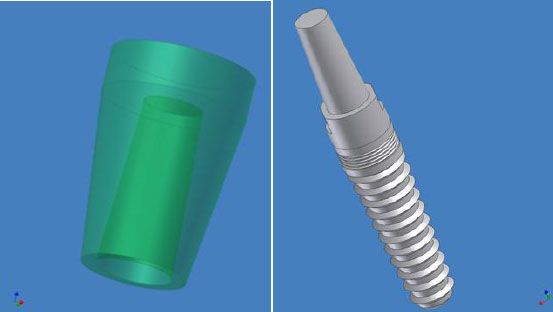
Implant-abutment complex and final design of superstructure (crown) geometries.
Both bone types, “cortical and spongy,” in addition to the gingival structure, were represented in the 3D model as three co-axial cylinders. The outer cylindrical shell of 1 mm thickness represented the cortical bone, which was filled by a solid cylinder of 14 mm diameter and 22 mm height of spongy bone. The cortical and spongy bones were separated using Boolean operations, and both bone structures were displayed in different colors [21]. While a mucosa of 2 mm thickness was placed on top of the cortical bone, the three structures were modeled using the finite element package GUI. The implant-abutment complex, bone, gingiva, and restorative crown represented the maxillary premolar region.
Using the finite element package ANSYS version 16 (ANSYS Inc., Canonsburg, PA, USA), a set of Boolean operations was performed between the solid modeled components of the model to create common surfaces to transfer the applied loads and finalize the geometric model. All materials used in this study were assumed to be homogeneous, isotropic, and linearly elastic. The materials used in this study are listed in Table 1. The material property values were imported into the finite element package [22-28]. Poisson’s ratio and modulus of elasticity for all materials utilized in this study are presented in Table 2.
| Material | Product and Manufacturer |
|---|---|
| Multilayered monolithic zirconia | (Ceramill® Zolid ht.+ preshade,Amann Girrbach, Koblach, Austria) |
| Polymer-infiltrated hybrid ceramic | Vita Enamic; VITA Zahnfabrik, Germany. |
| Lithium disilicate glass ceramic | IPS e.max CAD; Ivoclar Vivadent; Schaan, Liechtenstein. |
| Material | Modulus of Elasticity (MPa) | Poisson’s Ratio | Ref. |
|---|---|---|---|
| Cortical bone | 13,700 | 0.35 | [23] |
| Spongy bone | 1,370 | 0.35 | [23] |
| Titanium Implant | 110,000 | 0.35 | [23] |
| Gingiva | 19.6 | 0.30 | [24] |
| Resin cement layer “50 μm.” | 8,000 | 0.33 | [25] |
| Multilayered zirconia1 | 210,000 | 0.26 | [26] |
| Lithium disilicate glass-ceramic2 | 95,000 | 0.20 | [27] |
| Polymer-infiltrated hybrid ceramic or Vita Enamic)3 | 30,000 | 0.23 | [28] |
1.Ceramill® Zolid ht.+ preshade, Amann Girrbach, Koblach, Austria.
2. IPS e.max CAD; Ivoclar Vivadent; Schaan, Liechtenstein
3.Vita Enamic; VITA Zahnfabrik, Germany
The model components were meshed using the solid 185 (8-node) element type, which possesses three degrees of freedom corresponding to translations in the global X, Y, and Z directions. A mesh refinement test was conducted regularly before analysis to ensure the validity of the stress results. Refining the mesh by increasing the number of nodes and elements will improve solution accuracy, but at the same time, dramatically increase analysis time and computational resources. The resulting numbers of nodes and elements are presented in Table 3.
| Structure | Nodes | Elements |
|---|---|---|
| Crown | 8,786 | 5,539 |
| Cement layer | 8,519 | 4,164 |
| Implant - Abutment | 50,589 | 33,737 |
| Gingiva | 22,737 | 14,608 |
| Cortical bone | 170,132 | 110,031 |
| Spongy bone | 96,655 | 65,916 |
The final model, with an appropriate mesh size, is shown in Fig. (2a and b) and was generated using ANSYS.
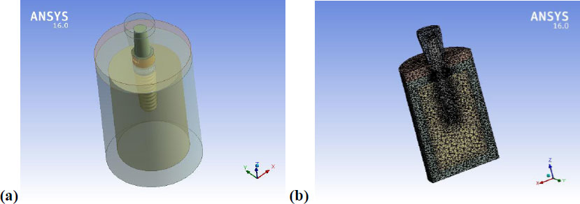
(a) 3D finite element model, (b) cross-section through the model
Complete osseointegration (100%) was assumed between the implant and bone via the bond interface [28, 29]. 21,22 The base of the hollow cylinder, “cortical bone,” was fixed in all directions as a boundary condition. Simultaneously, the model received a static occlusal load of 100N applied at the superstructure (crown) center, the “central fossa” [5]. Two distinct loading scenarios were used: the first as vertical compressive loading, and the second as 60º (non-axial) compressive oblique loading, simulating the clinical scenario of chewing (tearing load condition) in the palatal direction on the central fossa. Therefore, six case studies were conducted, in which each superstructure material was subjected to oblique and vertical loadings.
The modeling and finite element analysis in this study were conducted on a Workstation, an HP Z820, equipped with Dual Intel Xeon E5-2660 2.2 GHz processors and 64GB RAM. The stress distribution in the implant-abutment complex and restorative crowns (superstructures) was evaluated using von Mises stress (maximum equivalent stress) analysis.
3. RESULTS
Six stress analyses were conducted for the model, with two runs for each material: under one loading scenario (1) vertical and (2) oblique at 60º. The total deformation and the maximum von Mises stress were measured and recorded for comparison.
 The results obtained in this study for each component were defined as follows:
Svon is the von Mises stress (the maximum equivalent stress in MPa), and Usum is the total strain (total deformation) in mm. Figure (3a-f) shows a sample of the results obtained by applying a vertical load of 100N to the central fossa of the lithium disilicate glass-ceramic crown.
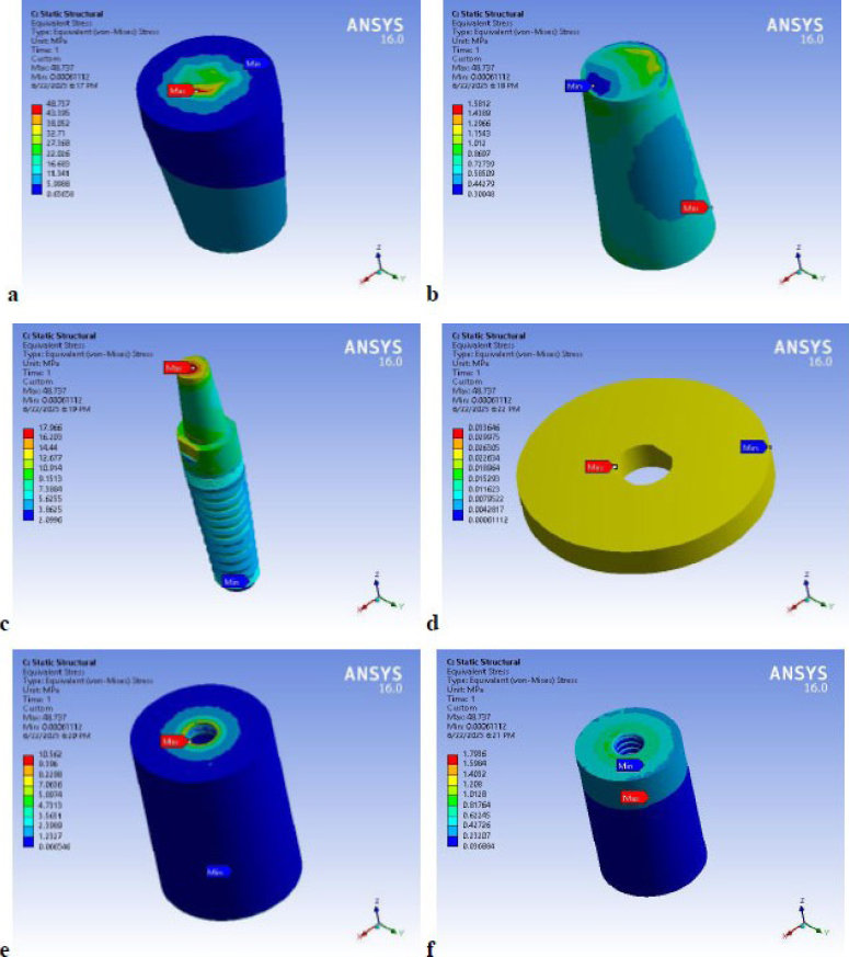
Sample of von Mises stress distribution on the model components “Lithium disilicate crown” under vertical load; (a) crown, (b) cement layer, (c) implant complex, (d) gingival, (e) cortical bone, (f) spongy bone.
The crown and implant complex exhibited the maximum von Mises stress at the loading site, as shown in Fig. (3a-c). In contrast, the cement exhibited the maximum value at the cement layer finish line, as shown in Fig. (3b), the gingival model component showed high von Mises stress, the cortical bone crest showed the maximum von Mises stress at the implant connection, and the spongy bone showed the maximum von Mises stress at the implant tip, as shown in Fig. (3d-f) respectively. Minor differences in deformations and stress distributions were observed: “under the same loading scenario.” At the same time, the values were altered by changing the crown material on the crown body, cement layer, and implant complex.
3.1. Material Performance under two Loading Scenarios
Three crown materials tested were Multilayered Zirconia (MZ, Lithium Disilicate, and Polymer-infiltrated Hybrid Ceramic. As presented in Fig. (4a and b), respectively, under both vertical and oblique loading, Multilayered Zirconia “MZ” crowns consistently exhibited the lowest deformations. Lithium Disilicate crowns showed intermediate deformation, while polymer-infiltrated hybrid ceramic crowns demonstrated the highest deformation. This indicates that zirconia provides the most rigid and stable superstructure among the tested materials. A significant finding was that oblique loading produced approximately 20 times the deformation of vertical loading. Despite this increase, the overall deformation values were described as 'fairly small' and did not suggest a critical condition or failure.
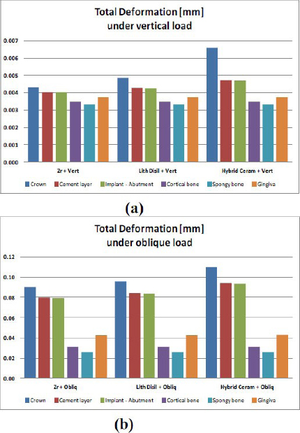
Total deformation comparisons on all components of the model; (a) under vertical loading, (b) under oblique loading for the three crown materials.
This underscores the importance of accounting for non-axial oblique loads in dental implant design and material selection. Vertical loads exert less stress, (Fig. 5a), and Oblique loading exerted stress higher than vertical loading on all model components, (Fig. 5b) (crown materials, cement layer, implant-abutment, cortical bone, spongy bone, and gingiva) by approximately 5-10 times more.
von Mises stress is a critical indicator of material yielding and potential failure. Figure 5 shows, the Multilayered Zirconia crown exhibited the lowest von Mises stress, approximately 10% lower than that of the other two materials. The trend was inverted under oblique loading, where multilayered zirconia crowns showed significantly higher von Mises stress (50% to 160% more) compared to Lithium Disilicate (LD) and Polymer-infiltrated Hybrid Ceramic crowns (PHC), respectively.
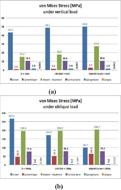
von Mises stress comparisons on all components of the model; (a) under vertical loading, (b) under oblique loading for the three crown materials.
3.2. Cement Layer
von Mises stress of cement under a Multilayered Zirconia crown was the lowest, followed by lithium disilicate; the hybrid ceramic showed the highest stresses on the cement layer under both vertical and oblique loading conditions. The cement layer generally exhibited low stress under vertical loading (not exceeding 3 MPa), indicating a safe condition with respect to cracking and failure. However, oblique loading increased cement layer stresses by 3-4 times, reaching critical values (50-70 MPa) under Lithium Disilicate and Polymer-infiltrated Hybrid Ceramic crowns.
3.3. Implant-abutment Complex
whatever the loading case, the implant complex showed increasing stresses from Multilayered Zirconia to Lithium Disilicate to Polymer-infiltrated Hybrid Ceramic by about (15.2 MPa, 18.0 MPa, and 27.5 MPa). Although the oblique load increased the stress on the implant by approximately 10-fold, the stress levels (approximately 200 MPa) remained within the safe zone for titanium implants, suggesting no risk of sudden failure under these loading conditions.
3.4. Cortical Bone
With a change in the crown material, minor deformation was recorded, with a maximum of approximately 0.03 mm under vertical and oblique loads. The cortical bone received approximately 10.5 MPa of stress under vertical load and 78 MPa under oblique load. The induced stress under vertical and oblique loads remained within the physiological limits of the cortical bone. However, with an oblique load, stress might approach the fatigue limit of the cortical bone, “indicating fatigue failure by time. The spongy bone and mucosa showed minimal sensitivity to changes in the crown materials. Regarding the comparative analysis for all the tested materials, as demonstrated in the summary table comparing stresses/deformations for all materials, presented in Table 4.
| Ut | Zr + Vert | Lith Disil + Vert | Hybrid Ceram + Vert | Zr + Obliq | Lith Disil + Obliq | Hybrid Ceram + Obliq |
|---|---|---|---|---|---|---|
| Crown | 0.0043 | 0.0049 | 0.0066 | 0.0902 | 0.0961 | 0.1101 |
| Cement layer | 0.0040 | 0.0043 | 0.0047 | 0.0798 | 0.0843 | 0.0941 |
| Implant - Abutment | 0.0040 | 0.0043 | 0.0047 | 0.0795 | 0.0839 | 0.0936 |
| Cortical bone | 0.0035 | 0.0035 | 0.0035 | 0.0310 | 0.0311 | 0.0313 |
| Spongy bone | 0.0033 | 0.0033 | 0.0033 | 0.0258 | 0.0259 | 0.0260 |
| Gingiva | 0.0037 | 0.0037 | 0.0037 | 0.0424 | 0.0426 | 0.0430 |
| Svon | Zr + Vert | Lith Disil + Vert | Hybrid Ceram + Vert | Zr + Obliq | Lith Disil + Obliq | Hybrid Ceram + Obliq |
| Crown | 43.3 | 48.7 | 49.8 | 267.5 | 172.9 | 99.7 |
| Cement layer | 1.1 | 1.6 | 2.7 | 46.3 | 51.1 | 64.0 |
| Implant - Abutment | 15.2 | 18.0 | 27.5 | 196.6 | 196.9 | 204.2 |
| Cortical bone | 10.5 | 10.6 | 10.6 | 77.6 | 78.3 | 79.2 |
| Spongy bone | 1.8 | 1.8 | 1.8 | 4.0 | 4.1 | 4.1 |
| Gingiva | 0.033 | 0.034 | 0.033 | 0.301 | 0.307 | 0.310 |
| Smax Principal | Zr + Vert | Lith Disil + Vert | Hybrid Ceram + Vert | Zr + Obliq | Lith Disil + Obliq | Hybrid Ceram + Obliq |
| Crown | 8.1 | 8.6 | 9.0 | 229.5 | 142.9 | 90.7 |
| Cement layer | 1.1 | 1.5 | 2.3 | 63.6 | 63.8 | 53.4 |
| Implant - Abutment | 10.6 | 10.6 | 10.6 | 246.0 | 232.4 | 248.3 |
| Cortical bone | 8.1 | 8.1 | 8.1 | 87.9 | 88.8 | 89.9 |
| Spongy bone | 0.997 | 0.997 | 0.997 | 4.1 | 4.1 | 4.2 |
| Gingiva | 0.000 | 0.000 | 0.005 | 0.4 | 0.4 | 0.4 |
| Smin Principal | Zr + Vert | Lith Disil + Vert | Hybrid Ceram + Vert | Zr + Obliq | Lith Disil + Obliq | Hybrid Ceram + Obliq |
| Crown | 87.0 | 86.0 | 86.4 | 206.4 | 129.6 | 94.1 |
| Cement layer | 1.6 | 2.1 | 4.2 | 62.7 | 63.2 | 54.7 |
| Implant - Abutment | 19.7 | 19.7 | 23.9 | 231.3 | 217.9 | 235.2 |
| Cortical bone | 14.1 | 14.1 | 14.2 | 104.9 | 105.9 | 107.0 |
| Spongy bone | 1.7 | 1.7 | 1.7 | 4.4 | 4.5 | 4.5 |
| Gingiva | 0.0 | 0.0 | 0.0 | 0.4 | 0.4 | 0.4 |
4. DISCUSSION
In the present study, the effects of three different restorative crown materials on stress distribution were evaluated in a single implant-supported restoration. According to the study findings, under vertical or oblique loading, the stress distributions in the gingiva, spongy bone, and cortical bone were similar across all restorative crown materials (Multilayered Zirconia, lithium disilicate, and polymer-infiltrated hybrid ceramic).
Moreover, the current study reported that a hybrid ceramic with a lower elastic modulus did not favor stress distribution in the implant-abutment complex and surrounding vital structures. Therefore, the hypothesis that a hybrid ceramic implant-supported superstructure would distribute stress more favorably than multilayered zirconia and lithium disilicate ceramics was rejected. While the stiffer materials may put more stress on the bone/implant interface (which can be mitigated by good implant integration and fit), the more flexible materials, like hybrid ceramics, are more prone to cohesive fractures within the crown structure.
Dental implantation has become a standard procedure with high success rates, relying on osseointegration between the implant surface and surrounding bone tissue. The selection of prosthetic restorative material depends on its ability to withstand masticatory forces and on its esthetic outcome. Implants and natural teeth respond differently to masticatory forces [2]. Direct in vivo measurement of stress distribution and strain analysis of superstructure materials is difficult. Nevertheless, a well-known theoretical method, Finite Element Analysis (FEA), for calculating stress distributions in complex structures is superior to other methods, including photoelastic stress analysis, a mathematical analytical process, and strain-gauge stress analysis [22]. Three-Dimensional (3D) FEA with standardized parameters, rather than 2D FEA, is widely regarded as the most powerful tool for simulating dental restorations under various loading conditions [22-29].
In the present study, ANSYS (a leading finite-element software) was used to construct a finite-element model with appropriate geometry and to analyze stresses [24-28]. Three-dimensional modeling was performed using a fine mesh with many elements (185 8-node elements) to represent the model components. To ensure sufficient validity of the stress analysis, a mesh-refinement test was performed repeatedly before the analysis [30]. Although mesh refinement yields more accurate results, it also increases computational time. However, it has been shown that element downsizing beyond a certain threshold does not provide extra information [31]. This study simulated a clinical chewing scenario under vertical, non-axial loading at 60° to the implant's longitudinal axis (tearing load), applying a 100 N load in the palatal direction to the central fossa of the upper premolar superstructure. The load (100 N) applied to the restorative crowns in this study was considered within the physiological load range of 17-450 N [32]. Moreover, this study is consistent with a previous study that reported that the direction of loading plays an essential role in determining stress levels [33]. The results were reported as strain and von Mises stresses to simplify the analysis, as in the previous study [34].
Regarding the vertical load results shown in Fig. (5), Multilayered Zirconia (MZ), Polymer-infiltrated Hybrid Ceramic (PHC), and Lithium Disilicate (LD) exhibited nearly equal stresses (43.3, 48.7, and 49.8 MPa, respectively). The energy absorbed by the cement was distributed to the implant-abutment complex (i.e., to the abutment top, then cervically around the implant-abutment neck, and finally to the implant tip). Stress was transmitted through the implant-abutment complex, with insignificant stress transferred to the spongy bone (0.03 MPa) and cortical bone (10.5 MPa), with a maximum stress concentration around the crestal region of the bone. Moreover, Oblique loading exerted stress higher than vertical loading on all model components (all crown materials, cement layer, implant-abutment, cortical bone, spongy bone, and gingiva) by approximately 5-10 times more than vertical load.
No considerable differences in deformations and stress distributions were observed “under the same loading scenario” with changing crown materials. Multilayered Zirconia “MZ” crowns consistently exhibited the lowest deformations. Lithium Disilicate crowns showed intermediate deformation, while Polymer-infiltrated Hybrid Ceramic crowns demonstrated the highest deformation. Figure 5 shows that the Multilayered Zirconia crown exhibited the lowest von Mises stress, approximately 10% lower than that of the other two materials. This may be attributed to zirconia's greater resistance to stress, rigidity, and stability under direct occlusal forces. However, the results were opposite under oblique loading, where multilayered Zirconia crowns exhibited significantly higher von Mises stress (50% to 60% more) compared to Lithium Disilicate “LD” and Polymer-infiltrated Hybrid Ceramic crowns “PHC”, respectively. This means that Polymer-infiltrated Hybrid Ceramic (“PHC”) received the least stress under oblique load. However, “PHC” is subjected to higher strain or deformation than the other two materials, “MZ” and “LD.”
This may be explained by the resin content of “PHC,” which imparts the material's elastic and bending properties. This property may be more susceptible to deformation, and the underlying components (cement layer, implant-abutment, cortical bone, spongy bone, and gingiva) may experience greater deformation than under vertical loads, as illustrated in Figs. (4 and 5). This explanation aligns with the study by Fabris et al. [35]. However, unlike previous studies, the present study suggests that a resilient superstructure material is beneficial for managing stresses around the implant [36]. Regardless of stress applied to the implant-abutment complex, implant failure is not expected when the von Mises stress is below the yield strength of a titanium implant, which is 550 MPa [37]. In oblique loading, all structures in this study (gingiva, spongy bone, and cortical bone) experienced higher stress & deformation than under vertical loading. This finding aligns with previous studies reporting that oblique loading poses a greater risk to prosthetic components and surrounding vital tissues, including spongy and cortical bone, than vertical loading. This may lead to strain or deformation of the gingiva and cortical bone [38]. The present study is consistent with a study that reported that stresses in cortical bone were generally higher than those in spongy bone [39]. Nevertheless, the ultimate tensile (100 MPa) and compressive strength limits (173 MPa) of cortical bone were not exceeded [40]. In the present study, high stress and strain were observed in the cervical area around the implant-abutment neck under both vertical and oblique loading. This result agreed with the study by Joseph et al. [41].
5. STUDY LIMITATIONS
Thus, the inherent limitation was that all materials tested were assumed to be linear elastic, homogeneous, and isotropic in the finite-element model. Moreover, load duration and the load's dynamic nature may be considered in future studies. Various restorative crown and abutment materials with lower elastic moduli may be considered in future studies. Different implant locations in the jawbone, accounting for varying bone density, should be measured in future research. Moreover, the crown design served as a cornerstone for subsequent superstructure designs in subsequent studies. In addition, static loading is typically used and is acceptable when stress levels are below the yield and fatigue limits. Finally, assuming complete osseointegration and simulating a crown without cusps were useful for eliminating any other factors or effects attributable to the source, except the study variables.
6. CLINICAL IMPLICATIONS
The clinical significance of these findings highlights a balance between the superstructure's material stiffness and static loading. Zirconia is generally considered a preferred material for high-load, implant-supported prosthesis in the posterior region due to its superior strength and favorable stress distribution characteristics for the implant and bone. It can withstand high masticatory forces. This was observed with variable levels of stress correlated with the type of bone tissue supporting.
CONCLUSION
Within the limitations of this study, the following conclusions were drawn:
(1) As the crown material changes from multilayered zirconia to lithium disilicate to polymer-infiltrated hybrid ceramic, there is growth in the stress and deformations of the crown body, cement layer, and implant complex. One exception was observed under oblique loading, where the trend was reversed.
(2) Oblique load exerted higher stress than vertical loading on all models' components by about 5-10 times greater.
(3) Cortical bone showed minor changes (about 1%), while spongy bone and mucosa showed insensitive reactions with changing crown materials.
(4) All stress values within this study were within physiological limits, and no sign of sudden or fatigue failure.
AUTHORS’ CONTRIBUTIONS
The authors confirm their contribution to the paper as follows: H.E., S.Y., M.A. and M.M.: Study conception and design; H.E.: Data collection; S.A., H.E., F.B. and K.K.: Analysis, and interpretation of results; M.A.: Draft manuscript; A.E., M.A., A.R. R.A.: All of the authors reviewed the results and approved the final version of the manuscript.
LIST OF ABBREVIATIONS
| FEA | = Finite Element Analysis |
| MZ | = Multilayered Zirconia |
| LD | = Lithium Disilicate |
AVAILABILITY OF DATA AND MATERIALS
The data and supporting information are available in the article.
ACKNOWLEDGEMENTS
Declared none.