All published articles of this journal are available on ScienceDirect.

Use of Digital Articulator in Implant Supported Prosthetics. A Case Report
Authors Info & Affiliations
Abstract
Introduction:
A case report is presented to demonstrate advantages of a new fully digital approach, from planning through to execution to immediate loading implant-prosthetic rehabilitation. Until now, the function of the diagnostic wax-up has not been assessable and the functionalization of the finished product, be it either a provisional or a definitive, has been entrusted entirely to the ability of the technician.
Case Description:
A female patient, unaffected by systemic disease and cranio-cervico-mandibular muscular pain, required removal of hopeless residual teeth of the upper arch and substitution with immediately loaded implants using guided surgery. A fully digital technique was performed using specific software to record individual condylar (axiography) movements and mastication cycles and to correlate these with initial intra-oral scans in order to create a virtual 3D individual value articulator. Seven implants were placed using guided surgery and the prosthetic rehabilitation was successfully performed as planned.
Conclusion:
The use of guided surgery guarantees atraumaticity and procedure predictability as documented in recent literature. However, in this case, for the first time, using the digital axiograph and digital articulator, it was possible to record the axiography of condylar movements in order to 'functionalize' the diagnostic wax-up prior to its insertion into guided surgery software. This clinical case suggests how the software's compatibility with intra-oral scan files, diagnostic wax-up, facial scans, CBCT and, in the near future, electromyography of mastication muscles permits the clinician to work on a virtual patient and analyze all critical aesthetic and functional parameters prior to guided surgery.
1. INTRODUCTION
Guided surgery is increasingly the first choice in modern implant dentistry. Advantages include software to insert implants 'virtually' and a 3D printed template to precisely guide drills and implants to a determined position. Additional advantages now exist due to improved software and hardware capabilities [1-4]. Guided surgery software has evolved and been accompanied by improvements in both Cone Beam Computed Tomography (CBCT) and 3D printing technology [5-9]. This enables 'virtual' implant placement, allowing precise decision making regarding the best implant position within the bone [1, 4] and eliminates implant positioning errors that are difficult to avoid when using a free-hand technique [2, 3]. Guided surgery software compatibility with Cone Beam Computed Tomography Digital Imaging and Communications in Medicine (CBCT DICOM) files and digital scanner Stereo Lithography (STL) files also enables on-screen analysis of the best implant position in the function of both available bone and advanced diagnostics [10].
The diagnostic wax-up is designed by the lab technician using Computer-Aided Design (CAD) technology to visualize future morphology and accurately analyze bone volume and the position of the patient's teeth [11]. The diagnostic wax-up is created with CAD software, starting with the patient's initial situation as revealed by either an intra-oral scan or by an analogical impression that is subsequently scanned in the lab.
The aim of the present case report is to present a fully digital technique using specific software to record individual condylar (axiographic) movements and mastication cycles, correlate these with initial intra-oral scans and create a virtual 3D individual value articulator.
2. CASE PRESENTATION
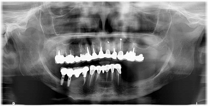
A 55 year-old female patient, non-smoker, unaffected by systemic disease, presented with an upper 17 to 25 metal-ceramic fixed partial prosthesis supported by irredeemable teeth. It should be noted that teeth 16 and 14 were extracted some weeks prior to guided surgery due to acute infection. Teeth 17, 13, 12, 11, 21, 22, 23, and 25 were extracted during surgery due to decay and periapical infection. Specifically, 17, 12, 21, and 23 demonstrated irreversible endodontic pathology, whilst 11, 22, and 25 demonstrated deep decay, and 13 exhibited a root fracture (Fig. 1).
Probing resulted in bleeding in at least 2 out of the 4 sites probed on each individual tooth. In particular, tooth 13 exhibited 12mm of probing. Evaluation of tooth mobility was not possible due to the presence of a full-arch fixture. The patient did not report cranio-cervico-mandibular muscular pain.
The patient's clinical condition indicated problems relating to the upper-arch fixture's supporting teeth and not relating to the temporo-mandibular articulation or muscles.
The treatment plan was the removal of the compromised residual teeth of the upper arch and substitution with immediately loaded implants using guided surgery.
2.1. Diagnostic Assessment
The patient's initial situation was revealed using an intra-oral scanner (Carestream 3600 Scan flow, Atlanta, GA, USA) [12]. The facial scan was performed using a Class 1 infra-red laser (DOF SNAP, DOF, Baekbong-ri, South Korea).
Axiography and mastication cycles were revealed using a digital axiograph (Prosystom P.Art, Sdi Matrix GmbH, Zurich, Switzerland). Elaboration of axiography Xlm files derived from the digital axiograph ((Prosystom P.Art, Sdi Matrix GmbH, Zurich, Switzerland) was performed using specific software (ExoCad Jaw Motion software, Excad Gmbh, Darmstadt, Germany).
Specific guided surgery software was utilized (Implant Geass, 3D Geass, Udine, Italy). The surgical template was printed by a printer (Voco SolFlex350 Printer, Voco Gmbh, Cuxhaven, Germany) with a resin (Voco V-Print SG Clear resin, Voco Gmbh, Cuxhaven, Germany).
The reinforced frame of the provisional was constructed using a light, chemically stable fiberglass disc (Trilor Bioloren, Saronno, Italy). The anatomical section was constructed using acrylic resin for temporary restoration (Structure CAD second generation resin, Voco Gmbh, Cuxhaven, Germany).
The first phase of treatment was digital information gathering in order to create a 'virtual patient' for subsequent insertion into guided surgery software. This phase began by taking an intra-oral scan (IOS) superior-inferior digital impression and bite block.
Two consecutive facial scans were then performed. The first facial scan was performed with an unforced natural smile and the second with a stent. The stent forms part of the DOF scanner (DOF SNAP, DOF, Baekbong-ri, South Korea) and is worn by the patient during this scan as described below. The frontal extra-oral section of the stent presents alpha-numeric codes. The horseshoe-shaped posterior section of the stent was fixed between the patient's teeth with polyether impression material (Impregum Penta Polyeter, 3M ESPE, Grassobbio, BG, Italy).
After both facial scans were performed, SNAP scanner software (DOF SNAP, DOF, Baekbong-ri, South Korea) artificial intelligence enabled the superimposing of the second scan, including alpha-numeric codes (reference points), onto the first scan performed with an unforced natural smile. The lab technician then superimposed the resulting double intra-oral scan files of the patient's initial situation onto the facial scan files. This process is completed in four distinct stages:
(1) A prototype 3D model of the intra-oral scan is printed
(2) The stent used during the facial scan is correctly positioned on the 3D model by using the polyether bite on the fork taken in the oral cavity.
(3) Together, the 3D model and the stent with alpha-numeric codes (reference points) is scanned.
(4) Using lab software, the facial scan files are superimposed upon the findings of the intra-oral scan. Together, these are superimposed upon the facial scan performed with the patient's natural smile.
The advantages of this technique, relative to standard 2D techniques, include not only improved visualization and 3D evaluation of aesthetic aspects of the treatment plan but also a series of diagnostic and therapeutic possibilities linked to progressive superimposition of CAD files. It is possible, in fact, to align the first intra-oral scan files with the diagnostic wax-up files within the facial scan.
Digital axiography data of condylar movements and mastication cycles is gathered during the creation of the virtual patient and, therefore, during the first phase. These two data sets are recorded separately. The first data set is recorded while the patient performs habitual lateral and protrusive mouth opening and closing movements. The second data set is recorded while the patient masticates a specific soft food substance.
The above data is obtained with digital axiography using:
(1) a small helmet positioned on the patient's head incorporating a video camera oriented downwards in the central section above the forehead.
(2) a fork in contact with the upper-arch incorporating a removable wireless technology 'marker' and alpha-numeric codes. These codes are printed on the marker and are oriented upwards towards the video camera. The correct relative position of the fork and the marker is obtained and secured by using aligned magnets.
(3) two stents with alpha-numeric codes are also oriented towards the video camera. These are temporarily fixed using composite material to the vestibular aspect of teeth 13 and 33.
2.2. Recording of Condylar Movements and Mastication Cycles
First, the position of the patient's upper-arch in 3D space is recorded by fixing the fork onto the upper teeth with polyether material. The fork is then 'associated' to the Central Marker by using a magnetic coupling. With the fork and the Central Marker in the correct position, it is possible to activate a wireless connection allowing communication between the Central Marker and digital axiograph (Prosystom P.Art, Sdi Matrix GmbH, Zurich, Switzerland). The combined Central Marker/fork unit allows the software to record the prosthetic plane inclination archived in the patient's clinical file.
The second step is to position the small helmet on the patient's head with the video camera oriented downwards to record the findings revealed by the Central Marker. The video camera reads the alpha-numeric codes on the Central Marker and automatically records the Central Marker's 3D position in space. With the Central Marker's alpha-numeric codes recorded, the software then instructs the clinician to position the stents on teeth 13 and 33.
Only at this point can the recording of the stents begin. The first stent is positioned on the vestibular aspect of tooth 13 with alpha-numeric codes oriented upwards towards the video camera for data and position recording purposes.
The second stent is positioned on the vestibular aspect of tooth 33, again with the alpha-numeric codes oriented upwards towards the video camera for data and position recording purposes. The software aligns the alpha-numeric codes with each successive recording. Specifically, the alpha-numeric codes of the stents are aligned with the alpha-numeric codes of the Central Marker, which in turn are aligned with the fork and which in turn is aligned with the model of the intra-oral scan.
Recording of condylar and mastication cycle movements occurs only after removing the combined Central Marker/fork unit. Condylar and mastication cycle movement recording begins with the patient in an initial position of maximum intercuspidisation. The patient is then asked to perform opening and closing, right and left lateral and protrusion movements.
The next recording is of mastication cycles. The software is activated and the patient is asked to masticate a specifically chosen particularly soft food substance such as a banana or chewing gum for 2 to 3 minutes. Recordings are observed on a monitor in real time and are represented graphically.
2.3. Intra-oral Scan and Axiography Association
The 'association' of the patient's intra-oral scan, condylar axiography, and mastication cycle movements is performed by a digital axiograph in a simple file alignment process.
First, a scan of the teeth/ polyether-fixed fork unit grouping is performed.
The next step is the creation of a 'Diagnostic Complex' of the patient using a digital axiograph. This consists of the alignment of all the information obtained from the patient resulting in a single exportable file compatible with and manipulatable in lab CAD software. When creating a Diagnostic Complex, the software first instructs the operator to align the scan files of the teeth/fork unit with the virtual fork present in the software. The virtual fork present in the software is the zero point upon which all the previously obtained relevant files are aligned in succession. The procedure of aligning the patient's teeth/fork unit file with the software's virtual fork is performed by simply nearing the two on-screen images using software tools. Artificial intelligence instantly snaps the two images to obtain the most accurate alignment possible.
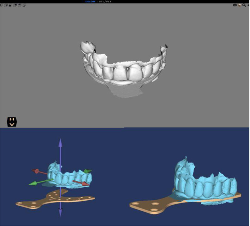
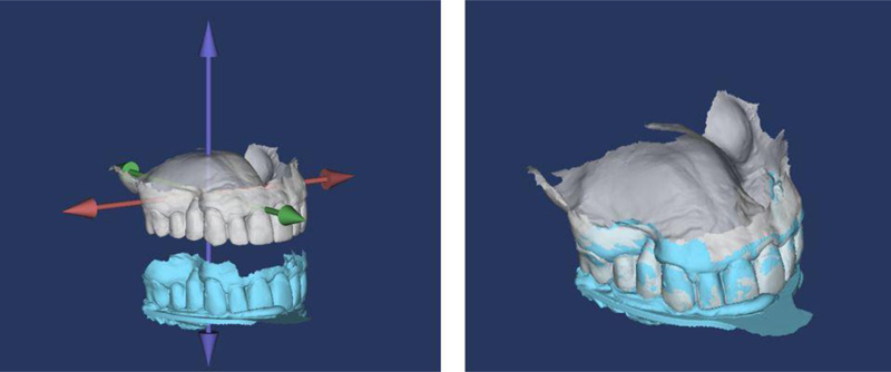
Now, the software's prosthetic plan, onto which all the other files are aligned, becomes the definitive prosthetic plan for the patient (Fig. 2). Once this first important passage is completed, the software asks the operator to 'associate' the intra-oral maxilla scan with the files of the new definitive prosthetic plan. The alignment of the files of the intra-oral scans with the definitive prosthetic plan is performed by bringing together the two on-screen images using software tools to automatically snap the two images to the best fit (Fig. 3). It is now possible to visualize the patient's personalized condylar axiography movements and mastication cycles in 3D 'associated' with the digital impressions in 3D (Fig. 4).
2.4. Exporting the Xml File
With the patient's diagnostic complex now complete, it is possible to export the XML files with all the acquired information and send them to the technician via e-mail. The patient's diagnostic complex is an 'articulator' of the patient's individual values, including movements around principal axes and mastication cycles.
2.5. Laboratory Phases
After sending the files to the lab, these are opened by software (ExoCad Jaw Motion software, Excad Gmbh, Darmstadt, Germany) and converted into CAD format using the Jaw Motion module (ExoCad Jaw Motion software, Excad Gmbh, Darmstadt, Germany).
In order to functionalize the diagnostic wax-up, it is moved virtually following the patient's recorded condylar trajectories and masticatory cycles. If any interference results, the software raises an alarm that indicates the specific cuspid of interference coloured in red. At this point, the technician deletes the red-alert zone until no diagnostic wax-up movement, and therefore no condylar movement raises the alarm.
Next the diagnostic wax-up is superimposed upon the facial scan performed with a natural smile aligning the functionalized diagnostic wax-up with the intra-oral scan, which was previously aligned with the facial scan (Fig. 5).
It is now possible to analyze every aesthetic aspect of the functionalized diagnostic wax-up.
The first phase ends with the team's and the patient's combined approval of the patient's new smile.
In the second phase of the treatment plan, optimal implant positions are identified using guided surgery software, analyzing bone availability and the functionalized diagnostic wax-up.
First the patient undergoes a CBCT exam wearing the universal stent (the intra-oral fork connected to an extra-oral geometry element comprised of three cubes), enabling the guided surgery software to align the DICOM files with the STL files. The fork is fixed between the patient's teeth with radio-transparent silicon with the extra-oral geometry element remaining outside the mouth.

After CBCT has been performed, the patient returns the fork to the clinician. At this point, the technician develops a 3D printed prototype model of the intra-oral scan. The technician then performs a scan of the 3D printed prototype model combined with the universal stent. The next steps are:
(1) Upload CBCT DICOM files into the guided surgery software.
(2) Upload of intra-oral and functionalized diagnostic wax-up Stl files. (These two steps are performed automatically by the software).
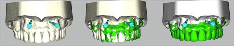
(3) Superimposition of DICOM and Stl files.
At this point, the software presents two distinct on-screen frames. The first frame shows CBCT DICOM file images with the stent visible, including the extra-oral geometries. The second frame shows Stl file images of the combined prototype model and stent. It is now possible to perfectly superimpose the two images by using the same extra-oral geometry reference points. Once this Best-Fit image has been obtained, it is possible to precisely align all the scans that have previously been taken.
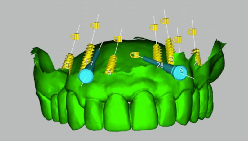
The next step is the virtual positioning of implants performed with glass 3D software (Fig. 6). The software generated implant-prosthetic treatment plan for this patient, indicating the virtual positioning of seven implants. The chosen sites were 12-22, 23, 14-24, 16-26 for immediate loading (Fig. 7). The next phases are:
(1) Design and manufacture of the surgical template (performed digitally).
(2) Design and manufacture of the provisionals using CAD and surgical intervention with immediate prosthetic delivery.
The surgical template is digitally designed in order to facilitate ease of positioning and optimum stability guaranteed by support from the mucosa. Housing spaces for the guide-rings are also considered. The drill and implant guide-rings and also the fixing pin guide-rings are luted in their specific positions, assisted by slides and stops.
2.6. Production of Provisional and Frame-work
This procedure is performed using CAD, reducing the diagnostic wax-up, creating a second Stl file for the framework. The frame-work design must consider the chosen material in terms of thicknesses and associated characteristics.
2.7. Therapeutic Intervention
The third and final phase of the implant-prosthetic treatment plan is the surgical intervention and luting of the provisional for immediate loading.
At the time of the surgery, after preventive antibiotic medication (amoxicillin 1g twice a day for six days), under local anesthesia (4% articaine solution with adrenaline 1:100,000 (Artin, Omnia, Fidenza, Italy)), the patient's prosthesis is removed and the surgical template supported by the mucosa is then correctly positioned. The drill is then passed through the fixing pin guide-rings. Once all the fixing pins have been inserted, the template fits perfectly in the correct position.
With the template inserted, it is now possible to create the seven surgical sites into which the implants will be inserted.
Drills are employed according to the surgical protocol to obtain surgical sites of diameter and length pre-established by the implants (Volution, i-RES, Lugano, Switzerland). Implant insertion is performed, reaching an insertion torque of 35N/cm for each implant.
The prosthetic phase for immediate loading requires the screwing of provisional abutments to the specific torque recommended by the manufacturer. The provisionals are then luted with auto-polymerizing cement applied onto every single temporary abutment. The passivation of the provisional is guaranteed when being luted to the temporary abutments. The position of the provisional is guaranteed by the presence of stops that rest on the shoulder of the temporary abutment. These two features guarantee both a healing process without tension between implants and the correct position of the provisional as planned in the digital project.
2.8. Follow-up and Outcomes
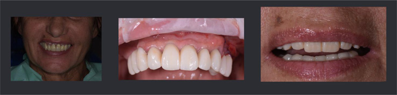
Seven implants were placed using guided surgery and the rehabilitation was successfully performed as planned (Fig. 8). The patient referred no post operative pain and no swelling was described. The patient was fully satisfied with the therapeutic outcome. Periodic follow ups were performed immediately after surgery, at 15 days, at one month, three months, and six months.

3. DISCUSSION
Aesthetics and function are fundamental aspects of diagnostic planning. Regarding aesthetics, the most advanced digital systems are utilized in the pre-visualization phase. Smile Design software and facial scanners, for example, are now well integrated into lab CAD systems [13-15], allowing analysis of the diagnostic wax-up within the face of the patient in both 2D and 3D. Regarding diagnostic wax-up functionalization, modern lab software simulates standard mastication dynamics. The virtual prosthetic plan, therefore, becomes functionalized only after it has been performed and the prosthesis inserted. Functionalization thus depends upon the clinician's ability to balance the prosthesis and, in part, patient adaptability to wear the prosthesis well over time.
The functionalized diagnostic wax-up is valid support in prosthetic implant rehabilitation. The possibility to visualize the prosthetic outcome in a 2D photograph and in a 3D facial scan is a valid support for the clinician and of great assistance when communicating with the patient. Furthermore, after years of technological evolution, it is now possible to align the future position of the patient's teeth using radiographic images inside guided surgery software platforms [10]. This enables the clinician to choose the correct implant position based on the quantity and quality of available bone and the functionalized diagnostic wax-up.
The limits up to the present have been that the diagnostic wax-up has constituted the ideal position and form of the patient's teeth and that the only assessed and assessable aspect has been the aesthetic outcome.
Until now, the function of the diagnostic wax-up has not been assessable and the functionalization of the finished product, be it either a provisional or a definitive, has been entrusted entirely to the ability of the technician and especially the clinician. This has been, throughout the years, the weak link in an otherwise near perfect chain.
It is now possible for the first time to record the axiography of condylar movements, to 'functionalize' the diagnostic wax-up prior to its insertion into guided surgery software. The software's compatibility with intra-oral scan files, diagnostic wax-up, facial scans, CBCT and, in the near future, electromyography of mastication muscles permits the clinician to work on a virtual patient and analyze all critical aesthetic and functional parameters prior to surgical intervention.
CONCLUSION
The limitation of this present article is that it refers to a single case. Further investigation is required in a larger sample size in order to confirm the findings presented.
LIST OF ABBREVIATIONS
| STL | = Stereo Lithography |
| CAD | = Computer-Aided Design |
ETHICS APPROVAL AND CONSENT TO PARTICIPATE
Not applicable.
HUMAN AND ANIMAL RIGHTS
Not applicable.
CONSENT FOR PUBLICATION
The patient gave informed consent.
STANDARDS OF REPORTING
CARE guidelines and methodologies were followed.
AVAILABILITY OF DATA AND MATERIAL
Not applicable.
FUNDING
This study was self-funded.
CONFLICT OF INTEREST
The authors declare no conflict of interest, financial or otherwise.
ACKNOWLEDGEMENTS
The authors wish to thank Salvatore Belvedere, Dental Technician, Milan, Italy.