All published articles of this journal are available on ScienceDirect.

A Three – Dimensional Finite Element Analysis of Polyetheretherketone PEEK in Dental Implant Prosthesis: A Novel Implant System
Abstract
Purpose:
This current numerical investigation aim to evaluate the benefits of substituting Titanium with CRF- PEEK for better stress distribution in implant- bone interface.
Methods:
3D models of a dental implant for the first mandibular molar were constructed using the computed tomography (CT) scan. Four distinct models using a combination of titanium, carbon reinforced polyetheretherketone (CRF- PEEK), and zirconia for implant /abutment materials were studied. A three- dimensional finite element simulation was used to evaluate the stress distribution at the implant – bone interface under a compressive axial load of magnitude 120 N. A spherical indenter was used to simulate occlusal load.
Results:
Mesh independent study was converged for a very large number of elements. Finite element analysis showed: 1) there was no significant difference in the distribution pattern of stress at the implant – bone interface in the different material models studied, 2) the stress values for all prosthetic implant parts were well below the yield strength, 3) a larger deformation of PEEK implant versus titanium.
Conclusion:
The substitution of titanium with PEEK for the implant does not provide any better stress distribution and may lead to problems from the deformation of the implant.
1. INTRODUCTION
Dental implantation has been used to restore lost teeth effectively for many years all around the world. The success is due in large part to osseointegration, a term coined by Brenmark in 1952.Mechanical features of the implant, such as mechanical stability, tensile and compressive strength, and stress distribution at the implant-bone interface, all play a role in its long-term stability [ 1]. Despite the high clinical success rate, dental implants are still receiving attention from many researchers investigating its different aspects. The stress distribution at the bone –implant interface is considered one of the key elements in determining dental implant stability.
The sources of implant failure are basically categorised as biological and mechanical. The biological failure can generally refer to poor osseointegration process, whether in early or late stages post implantation, due to several factors, including surgical trauma, infections, and inflammations like peri-implantitis [2, 3]. The other main source of implant failure is the mechanical breakdown of any dental implant components that manifest as damage and/or fracture of the implant body, implant abutment, and the implant screw (Goodacre et al. 2003) [4]. Previous research has indicated that implant fracture is the most common cause of general mechanical complications and that this is a time-dependent phenomenon. It is noteworthy to mention that most fracture cases were recorded 5 years after loading; screw fracture is most commonly encountered with a range of 9.3%- 18.5%, while the implant body fracture was found to be rare with 4% after 5 years of loading (Simonis et al., 2010) [5].
Mechanical complications are strongly associated with the magnitude and direction of the mastication loads and the subsequently generated stresses. The major effective element of the implant loading is the occlusal load magnitude. Additionally, parafunctional habits like clenching and bruxism may accelerate the stress generated between implant and superstructure prosthesis, resulting in untimely mechanical complications (Pérez, 2012) [6]. Metal fatigue is reported to be the key reason for implant fractures which is mostly attributed to cyclical episodes of mastication load. Numerous studies investigated the importance of the implant design on the failure rate. It has been found that there is a strong link between mal-design and stress concentration within the implant components. Remarkably, the Finite Element Method (FEM) was found to be an effective design tool to simulate the loading protocols on implants by integrating both geometrical and material factors.
The direct effect of occlusal loads properties on stress distribution in implants was previously confirmed. Maximum stress values generated by various loadings modes such as static, dynamic, and fatigue were fortunately reported to be lower than the yield strength of the abutment and implant/abutment joining screw (Kayabas et al., 2006) [7]. However, despite the adequacy of their microstructure, titanium-based dental implants fractured when overloaded [8].
Implant abutment connection geometry was claimed to play an important role in distributing the stress throughout the body of the implant. Axial loading of implants did not produce a significant difference between ” internal” and ” external” implant abutment connection design. However, off-axis loading increased tensile stresses in the screw threads of the external-connection implant, while stress was reduced with an internal-connection (Merz et al., 2000) [9]. These findings were supported by in vitro study. In disagreement with the aforementioned studies, Piermatti et al. reported that the screw diameter was more relevant to maintaining screw preload compared to the type of abutment junction (Piermatti et al., 2006) [10].
The revolution in digital dentistry and dental technology fields has introduced novel technologies and enhanced the industry to provide new materials pivoting on the biocompatibility characteristics of the material and the mechanical behaviour and properties. Pure titanium and titanium alloy served as the only implant material for decades due to its strength, highly resistance to fatigue, low density, resistance to corrosion, and the main reason why titanium is often used in the body is its superior titanium biocompatibility (Osman and Swain, 2015) [11]. Titanium implant abutments, on the other hand, have been seen to have an unfavourable greyish colour and may cause problems when they become visible. Allergic responses appear to be another significant disadvantage since it is not reactive with the oral environment (Gahlert et al., 2012) [12].
In recent years, zirconia (ZrO2) has been employed as dental implants abutment alternative for its optimum properties (Brakel et al., 2011) [13]. Moreover, beneficial properties for zirconia like its translucency and white colour mimic the natural teeth. Also, studies found that zirconia provides a superior biological response over titanium (Canullo, 2007) [14]. On the other hand, Mitsias et al., 2010, compared titanium abutment with zirconium abutments and concluded that the titanium abutment showed significantly better behaviour [15]. As regards the reliability of both types of abutments, titanium abutments showed a 100% reliability rate whereas zirconium abutments lost reliability as the load was increased up to 400 N.
Most recently, polyetheretherketon (PEEK) and the reinforced versions of this polymer like the carbon reinforced (CRF-PEEK) have invaded the dental materials industry to benefit from the shock absorbing property of PEEK material, which claimed to act as bone protection. Whilst, using rigid structure implants, such as titanium, will transfer stress onto the bone and result in resorption, leading to catastrophic implant failure.
The most attractive characteristic that highly encourages the use of PEEK in medical and dental fields is having low elasticity modulus (3-4 GPa), which is close to that of bone (Ma and Tang, 2014) [16]. It is anticipated that using a PEEK with low modulus of elasticity will reduce the stresses of the dental prosthesis and surrounding tissues. Thus, enhancement of the success rate and the prognosis of any prostheses is achieved. This polymer has superior biocompatibility where no allergy, toxicity, or mutagenic effects exist; therefore, it has been introduced to overcome the metallic allergy of titanium (Stephan et al., 2013) [17]. Obviously, the low density of PEEK causes a high strength to weight ratio; this is a fascinating advantage of any restorative and prosthetic material since it enables the frameworks and other parts included in dental prosthesis to be fabricated as a whole unit without generating excessive load on the tissues (Eltas, 2015) [18].
In recent years, numerical analysis has been thoroughly utilized to predict biomechanical behaviour of different geometrical parameters in addition to assessing the newly available materials incorporated in the dental implant. The obvious benefit of this analysing method is to solve complicated structural drawbacks in dental implant systems by using digital mathematical techniques (Ma and Tang, 2014) [17]. The aim of this current numerical investigation is to evaluate the benefits of substituting titanium with CRF- PEEK for better stress distribution in implant- bone interface. FEA is used to determine the stresses in the implant system under axial compressive load.
2. MATERIALS AND METHODS
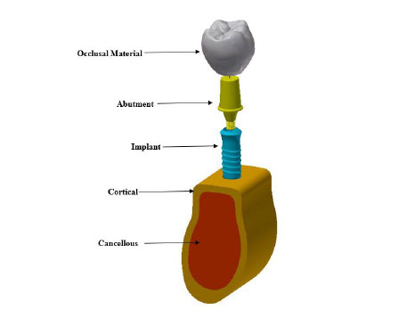
A 3D model of dental implant placed in the first mandibular molar segment section is built. The mandibular molar section and its superstructure are digitized with computed tomography (CT) scanner. The generated stereolithography (STL) files are imported into the commercial solid modeling software (solid work 2018). The implant and abutment connections are created using solid works 2018. The implant system was then imported in a finite element software package ANSYS 18.1 for FEA execution. Fig. (1) shows the 3D model of the implant. A Ø 4.1 mm × 12 mm single threaded tapered implant with morse tapered connection is selected in this study. The chosen material for the crown is high translucent tetragonal zirconia polycrystals doped by yttrium (YZ-HT zirconia) (VITA In-Ceram, VITA North America, USA) (Vichi et al., 2016) [19]. The implant screw is placed vertically in a modeled cortical and trabecular bone.
Mesh refinement is applied to the various critical regions in the implant system. Fig. (2) shows the mesh of the FEM. These locations are mainly located at the occlusal surface and implant – bone interface. Mesh independent study is conducted to ensure that FEA results do not depend on the mesh density. The physical interactions between various parts of the dental implant are modeled through bonded surface-to-surface contact features of ANSYS 18.1. Behaviors of the crown, abutment, implant materials are modeled with linear isotropic material models, while, cortical and cancellous bones are modeled by an anisotropic material model (Eltas, 2015) [18]. Tables 1 and 2 list the mechanical properties of the various materials used in the 3D model. The effect of mechanical properties of materials on stress distribution at the implant–bone interface is evaluated by building four distinct models listed in Table 3.

| Modulus of Elasticity (Gpa) | Modulus of Rigidity (Gpa) | Poisson’s Ratio | |
|---|---|---|---|
| Cortical | Ex =12.7 | Gxy=5 | vx=0.18 |
| Ey= 17.9 | Gyz= 7.4 | vy=0.28 | |
| Ez=22.8 | Gxz=5.5 | vz=0.31 | |
| Cancellous | Ex=0.21 | Gxy=0.068 | vx=0.055 |
| Ey=1.148 | Gyz=0.434 | vy= 0.322 | |
| Ez=1.148 | Gxz=0.068 | vz=0.055 |
| Model # | Implant Material | Abutment Material |
|---|---|---|
| 1 | Ti 6AL 4V ELI | Ti 6AL 4V ELI |
| 2 | Ti 6AL 4V ELI | CFR-PEEK |
| 3 | CFR-PEEK | CFR-PEEK |
| 4 | CFR-PEEK | Zirconia |
Although the average masticatory forces range between 75 -100 N (Eazhil, 2016) [20], this force has dynamic nature rather than static under the oral environment conditions. Since this study performs static analysis, the dynamic effect is accounted for by adding 20% to static load. Hence, the implant was loaded axially with 120 N to account for the dynamic effect.
3. RESULTS
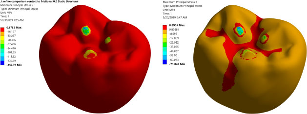
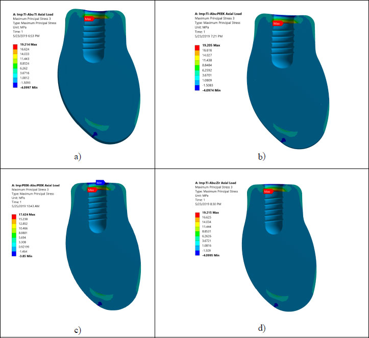
Prior to analyzing and judging the FEA results, the mesh independent test is conducted to ensure that the FEA results do not depend on element size. Table 4 summarizes the mesh independent study. Notably, a large number of elements are needed (3,680,403 elements) due to the complex shape of the occlusal surface of the first mandibular molar and the existence of threaded implants. This large element number assures accurate simulation of the load transfer to the region of interest. Fig. (3) displays the maximum and minimum principal stresses contours at the occlusal surface of the zirconium crown. It shows that there are three points of contact between the indenter and the occlusal surface of the crown.
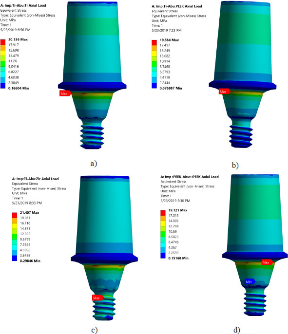
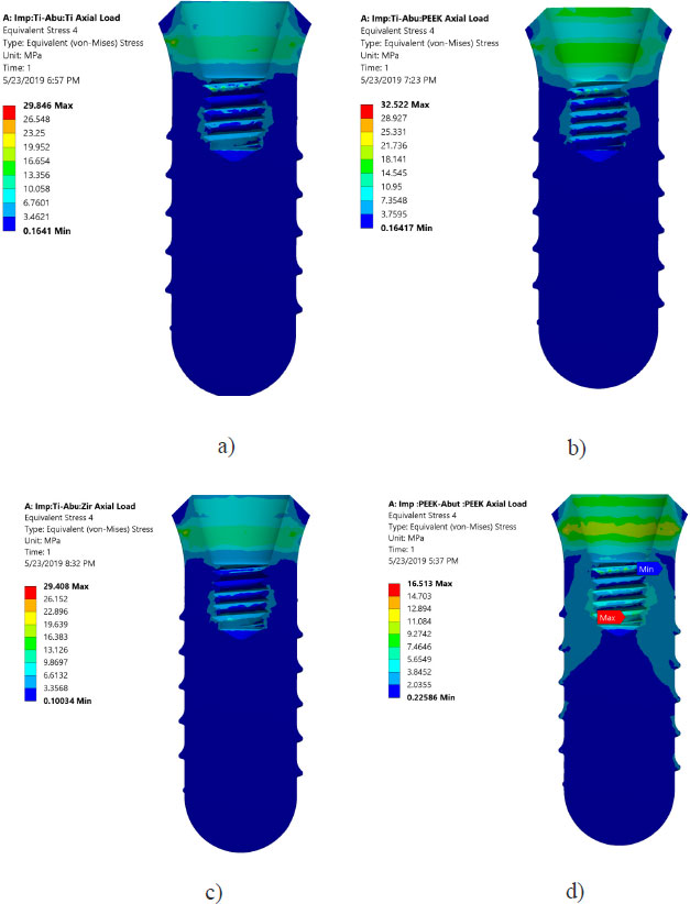
Von Mises stresses in the implant body and abutment for the district models are demonstrated in Figs. (4 and 5). It is clear that stress concentration is located in the abutment neck for PEEK and titanium, but for the zirconium abutment, the maximum stress is located in the first engaged thread of the abutment.
| No. of Element |
Von Mises Implant (MPa) |
- |
Maximum Principal Stress in Surrounding Bone (Max Tension) (MPa) |
- |
|---|---|---|---|---|
| 482,556 | 57.25 | 24.5 | NA | |
| 1,049,431 | 67 | 17.0 | 23.2 | 15.8% |
| 1,657,295 | 58.68 | 12.4 | 17.7 | 12.4% |
| 3,229,826 | 63.51 | 8.2 | 18.6 | -5.1% |
| 3,680,403 | 61.12 | 4.0 | 19.2 | -3.2% |
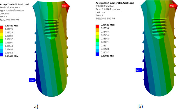
All investigated models express values of Von Mises stress below the strength of all materials used (numbers or refer to the table of mechanical properties of used materials). FEA results predict no significant difference in stress distribution among the different tested materials for both abutment and implant bodies. Fig. (6) indicates that the stress distributions at implant – bone interface for the 4 models studied are almost identical. Fig. (7) shows the total deformation in the peri-implant bone for the four distinct models studied. Table 5 summarizes the stress peaks in the different structures of the four distinct models studied.
| No. of Elements | Implant Material | Abutment Material | Von Mises Implant [MPa] | Von Mises Abutment [MPa] | Maximum Principal Stress Cortical/Medullar [MPa] |
Minimum Principal Stress Cortical/Medullar [MPa] |
|---|---|---|---|---|---|---|
| 396641 | Titanium | Titanium | 29.84 | 20.136 | 19.21/2.20 -4.09/-1.04 |
1.06/0.325 -20.74/-3.28 |
| 396641 | Titanium | CFR-PEEK | 32.52 | 19.58 | 19.20/2.209 -4.09/-1.04 |
1.06/0.325 -20.75/-3.28 |
| 396641 | CFR-PEEK | Titanium | 18.85 | 1tr7.7 | 23.494/0.722 -8.033/-0.338 |
1.10/0.22 -25.82/-3.39 |
| 396641 | CFR-PEEK | CFR-PEEK | 16.51 | 19.12 | 17.62 /3.95 -3.85/-1.54 |
1.02/0.495 -17.41/-3.82 |
| 396641 | Titanium | Zirconia | 29.40 | 21.40 | 19.21/2.20 -4.09/-1.04 |
1.06/0.325 -20.74/-3.28 |
4. DISCUSSION
Table 4 illustrates the mesh convergence of the maximum principal stress at the cortical bone and Von Mises stresses for the implant. Due to the complex shape of the chosen occlusal surface and the existence of threads, a large number of elements are needed. This large element will serve to accurately simulate the load transfer to the region of interest. Fig. (3) shows the maximum and the minimum stress distribution in the implant bone interface, which is an issue of great importance. Thus, intensive careful investigations are needed, as the protocol of transferring the applied load to the peri-implant bone determine the success rate of the dental implant.
Areas of stress concentration were found to be located in the implant neck of the different models except for PEEK abutment and PEEK implant, where the high - stress region was located close to the first engaged thread. These findings are in agreement with the previously published work of [21-24].
The values of Von Mises stress for all models are well below the ultimate strength of the chosen materials. This confirms that there is no threat of yielding or fracture in implants or abutments. The investigations of time dependent failure (fatigue failure) are highly recommended. Since peri-implant bone is brittle, maximum compression and maximum tensile stress values are necessary for the tested distinct models in this study.
Stress distributions at implant – bone interface for the 4 models studied were found to be almost identical. This suggests that different combinations of the materials studied have a negligible effect on load transfer to the peri-implant bone (agreement). However, it was hypothesized that using CFR-PEEK for implant/abutment, which has a much lower young modulus compared to metallic, will have better uniform distributions of stress in peri-implant bone. This unexpected result agrees with previous studies that tested polyoxymethylene in dental implants [10-13, 25-27]. It was suspected that studying the axial load does not show the effect of utilizing softer materials. However, previous studies showed that non-axial load is more harmful to dental implants than an axial load [25, 28-29]. But regarding the effect of utilizing softer materials than metallic, previous studies reported that utilizing CFR-PEEK for implant/abutment has a negligible effect on load transfer under non –axial load. The reasons behind this can be explained since static analysis does not consider the cushion behavior of softer material like PEEK. FEA predicts that there is no threat from yielding or fracture of implant prosthetic components under axial loading of 120 N. Finally, Fig. (7) shows that using PEEK for implant and abutment results in larger deformation than titanium implant and titanium abutment. The total deformation for PEEK implant- PEEK abutment ranges between 0.186 and -0.18 mm, while for titanium implant and titanium abutment, the deformation ranges between 0.138 and -0.134 mm. This suggests that PEEK performs worse than Ti under static load. The following are some of the limitations of this investigation: Low-temperature degradation, susceptibility to the presence of notches and irregularities, and the effect of pH fluctuations were not considered.
CONCLUSION
The masticatory forces that occurred in the oral conditions are simulated by an average compressive force equal to 120 N applied axially. The effect of several combinations of different materials used for fixture and abutments on implant stability is evaluated. The stress distribution around the implants after loading with average masticatory force was calculated by FEA. Present FEA results agree very well with previously published results. FEA results predict that utilizing material with similar strength to the bone does not provide any advantages in regards to better stress distribution to the peri-implant bone. These findings are in agreement with previous work.
AUTHORS' CONTRIBUTION
N.A conceived the ideas, led the writing, reviewed the results. K.B built the models, developed the theoretical formalism, supervised the findings of this work, performed the numerical simulations, investigated the models. All authors discussed the results and contributed to the final manuscript writing.
ETHICS APPROVAL AND CONSENT TO PARTICIPATE
Not applicable.
HUMAN AND ANIMAL RIGHTS
No animals/humans were used for studies that are the basis of this research.
CONSENT FOR PUBLICATION
Not applicable.
AVAILABILITY OF DATA AND MATERIALS
Data is available from the corresponding author upon request.
FUNDING
None.
CONFLICT OF INTEREST
The authors declare no conflict of interest, financial or otherwise.
ACKNOWLEDGEMENTS
The authors would like to thank Dr., professor in the Department of Applied Dental Sciences, for the advice on various technical and dental issues.