All published articles of this journal are available on ScienceDirect.
Comparison of the Stress Strain Capacity between Different Clear Aligners
Abstract
Background:
The rife use of aesthetic appliance in orthodontic treatment requires the study of the properties of the materials they are made of.
Objective:
The aim of the present study was to evaluate the dimensional stability of clear aligners made of three different materials after the application of in-vivo dynamic stress and in-vitro static stress.
Methods:
Three different aligners made of different materials (PET-G; PET; SmartTrack®), prepared on the dental arch of the same patient, were tested. For each material, three aligner samples were manufactured: one to be used in-vivo, one to be tested in-vitro, and one to be used as a control.
To evaluate the effects of the dynamic stress produced in-vivo, each aligner was worn by a single patient 22 hours per day, followed by a wash-out period of two weeks. To evaluate the effects of static stress, each aligner was exposed to the in-vitro continuous force of 50N. The tested and control aligners were scanned, then linear measurements were taken to evaluate their dimensional stability after different types of stresses.
Results:
PET seems to have the lowest percentage of deformation; PET-G and SmartTrack® showed a reduced deformation going from the posterior to the anterior area. The contact with human saliva induces a greater deformation.
Conclusion:
Different materials show different behavior following application of static stresses and dynamic stresses in the oral cavity. PET showed the highest dimensional stability.
1. INTRODUCTION
The demand for aesthetic orthodontic treatment is pconstantly growing [1], and this is leading to increased use of ceramic brackets [1], lingual brackets [2] and clear aligners [3]. The Clear Aligners (CA) are especially suited for aesthetic orthodontic treatment in adult patients [4]. This type of treatment is hygienic [5], reduces the perception of pain [6] and for this reason, generates more collaboration from the patients [7].
CA are produced in various materials such as: a new thermoplastic Polyurethane (SmartTrack®) [8], Polyethylene Terephthalate Glycol-modified (PET-G), Polycarbonate (PC), Thermoplastic Polyurethanes (TPU), Ethylene Vinyl Acetate, Polyethylene Terephthalate (PET), and other materials [9].
CA are used for orthodontic treatment in many types of malocclusion [10-13], with a suggested wear time of 22 hours per day, and a timespan of 15 days for aligners’ change [14]. One of the key factors for the clinical success of orthodontic tooth movement with CA is the stability and the retention of the aligners: to increase CA retention, many authors suggest using composite attachments on some teeth [15, 16]. Many studies evaluated the clinical effectiveness of CA [17-19], but less information is available from the literature regarding the dimensional modification and stability of CA during the 15 days wear period. The reduction in adaptation precision of the worn CA may reduce the precision in tooth movements.
The aim of the present study was to evaluate the dimensional stability of CA after two types of stresses: in-vivo stress during 15 days wear-time, and in-vitro compressive strain.
2. MATERIALS AND METHODS
One patient (male, 29 years of age) at the Orthodontic department of University of Foggia was selected and enrolled in the present study. The participant provided written informed consent to be involved in the study. The patient presented a moderate crowding of upper and lower incisors, no prosthetic rehabilitation, no fillings, no oral parafunctions, no Temporo-Mandibular Joint disorders, no periodontal infection and good oral hygiene.
2.1. Type of Investigations
Patient’s impressions were taken with Polyvinilsylossane material and sent to three different CA manufacturers to obtain a clinical setup and a set of aligners. This allowed to obtain three different sets of CA made of different materials: the SmartTrack® (Align Technology), PET-G, and PET. No attachments were used to increase the aligner’s stability. The thermoforming procedures in the present study were performed under the respective manufacturer’s recommended conditions, and all the aligners had the same thickness of 0.8 mm. The first aligner of each set was programmed as a passive aligner, without any tooth movement. Three copies of the first aligner were requested to each manufacturer, to have three samples of each material: One to be used in-vivo, one to be tested in-vitro, and one to be used as a control.
2.2. In-vivo Testing
One aligner of each material was worn by the patients for 15 days, 22 hours per day. A wash-out period of two-weeks was used between each use with different CA of a different manufacturer. The patient was instructed to wear the aligner for the recommended time, and to remove it during meals, during oral-hygiene procedures, and during the assumption of any liquids except water. The aligners were cleaned using only cold water and a soft toothbrush.
2.3. In-vitro Testing
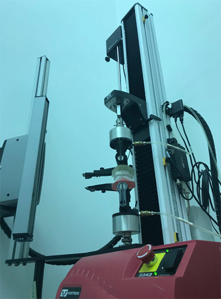
An additional set of patient’s impressions was used to produce a dental cast used for in-vitro testing. Dental casts were poured on a custom-made resin base, designed to be easily secured to the Instron machine (Fig. 1).

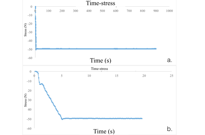
One CA of each material was set on the dental cast, then the casts were settled into occlusion and secured to an Instron 3343 universal testing machine with a loading cell of 1kN. A compressive force of 50N was applied (Fig. 2) during a 6 seconds increase, then applied constantly for 15 minutes (Fig. 3).
2.4. Comparison
At the end of the test, the tested and control aligners were covered with a 3D scan spray (Helling 3D Spray) then scanned using a laboratory scanner (3 Shape Scanlt Manager tps .Ink, 3Shape, Copenhagen, Denmark).
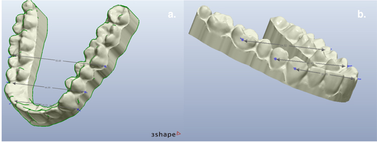
The scanned aligners were evaluated with a dedicated software (3 Shape Orthoviewer, 3 Shape, Copenhagen, Denmark). Two points were identified on right and left first molar (posterior area), first premolar (middle area), and canine (anterior area): vestibular apical point of dental crown, defined as “base of the tooth point” (BoT point), and the intersection point of vertical and horizontal axis, defined “facial axis point” (FA point). The authors measured the distance between right and left BoT points on first molar, first premolar, and canine, and the distance between right and left FA points for the same teeth (Fig. 4). These measurements were used to compare the dimensional stability of CA after in-vivo dynamic stress and in-vitro static stress within each material, and between different CA materials. To have a summary value for every material, the distances at the anterior, middle, and posterior parts for both in-vivo and in-vitro tested aligners were pooled and mean and standard deviation were calculated.

3. RESULTS
The differences at the BoT point and at the FA point are shown in Tables 1 and 2. Both Smart track® and PET-G presented at the BoT point the same deformation in dynamic and static stresses. PET had the lowest deformation at the BoT point and at FA point than the PET-G and Smart Track® (Tables 3-5) (Fig. 5). The difference was higher in the posterior part than the anterior part. SmartTrack® showed higher deformations than the PET in the static and dynamic test. PET-G had less deformation in the anterior area than the other materials. Examining the summary values of each material, in general PET showed the smallest deformation, followed by SmartTrack® and PET-G (Tables 4 and 5).


| Teeth Distance | Upper First Molar (16-26) | Upper First Pre-Molar (14-24) | Upper First Canine (13-23) | ||||
|---|---|---|---|---|---|---|---|
| Base-line distance in BoT point (mm) |
54,5 | 43,8 | 38,3 | ||||
| Smart Track® |
Test | Patient Stress | Instron Stress | Patient Stress | Instron Stress | Patient Stress | Instron Stress |
| Value (mm) | 56.66 | 55.69 | 45.47 | 45.02 | 38.97 | 38.84 | |
| Difference | + 2,16 | +1,19 | +1,67 | +1,4 | +0.67 | +0.54 | |
| PET-G | Test | Patient Stress | Instron Stress | Patient Stress | Instron Stress | Patient Stress | Instron Stress |
| Value (mm) | 57.46 | 56.27 | 45.43 | 45.30 | 38.66 | 39.13 | |
| Difference | +2,96 | +1.77 | +1,63 | +1,5 | +0,36 | +0.83 | |
| PET | Test | Patient Stress | Instron Stress | Patient Stress | Instron Stress | Patient Stress | Instron Stress |
| Value (mm) | 55.02 | 55.38 | 44.60 | 44.90 | 38.81 | 38.59 | |
| Difference | +0,52 | +0.88 | +0,8 | +1.1 | +0,51 | +0.29 | |
| - | Upper First Molar (16-26) | Upper First Pre-Molar (14-24) | Upper First Canine (13-23) | ||||
|---|---|---|---|---|---|---|---|
| Base-line distance in FA point (mm) |
54,1 | 43,8 | 37,7 | ||||
| Smart Track® |
Test | Patient Stress | Instron Stress | Patient Stress | Instron Stress | Patient Stress | Instron Stress |
| Value (mm) | 56.11 | 55.20 | 44.84 | 44.66 | 38.21 | 38.51 | |
| Difference | + 2,01 | +1,1 | +1,04 | +0,8 | +0.51 | +0.81 | |
| PET-G | Test | Patient Stress | Instron Stress | Patient Stress | Instron Stress | Patient Stress | Instron Stress |
| Value (mm) | 56.21 | 54.73 | 44.86 | 44.44 | 38.12 | 38.04 | |
| Difference | +2,11 | +0.63 | +1,06 | +0,64 | +0,42 | +0.34 | |
| PET | Test | Patient Stress | Instron Stress | Patient Stress | Instron Stress | Patient Stress | Instron Stress |
| Value (mm) | 54.89 | 54.59 | 44.04 | 44.07 | 38.00 | 38.26 | |
| Difference | +0,79 | +0.49 | +0,24 | +0,27 | +0,3 | +0.56 | |
| - | BoT Point | FA Point | ||||||||||
|---|---|---|---|---|---|---|---|---|---|---|---|---|
| - | Upper First Molar | Upper First Pre-Molar | Upper First Canine | Upper First Molar | Upper First Pre-Molar | Upper First Canine | ||||||
| - | Dynamic | Static | Dynamic | Static | Dynamic | Static | Dynamic | Static | Dynamic | Static | Dynamic | Static |
| SmartTrack® | + 2,16 | +1,19 | +1,67 | +1,4 | +0.67 | +0.54 | + 2.01 | +1,1 | +1,04 | +0,8 | +0,51 | +0,81 |
| PET-G | +2,96 | +1.77 | +1,63 | +1,5 | +0,36 | +0.83 | +2,11 | +0,63 | +1,06 | +0,64 | +0,42 | +0,34 |
| PET | +0,52 | +0.88 | +0,8 | +1.1 | +0,51 | +0.29 | +0,24 | +0,27 | +0,3 | +0,56 | +0,24 | +0,27 |
| BoT Point | SmartTrack® | PET-G | PET |
|---|---|---|---|
| Mean (mm) | 1,27 | 1,51 | 0,68 |
| Std. Deviation | 0,6 | 0,9 | 0,3 |
| Std. Error of Mean | 0,2 | 0,4 | 0,1 |
4. DISCUSSION
The first set up dental movement was described by Kesling in 1945 [20]. The use of occlusal splint in the upper and lower arch with a sequence of aligners induce a tooth movement which solves a malocclusion [21]. The first aligners used were too stiff and thus produced hard forces on teeth; double-layer foils replaced the single-layer foils featuring a highly elastic layer on the inner side of the aligner [22].
One of the greatest advantages is better oral hygiene during orthodontic treatment for both adults and adolescents [5]. On the other hand, the level of patient compliance is the greatest disadvantage [7]. For this reason, many manufacturers introduced a compliance indicator on aligners [23], to evaluate the effective use of the CA.
The dental movement may not be adequate for three reasons: the lack of patient’s compliance, the planning of an excessive amount of dental movement, the inadequate transfer of the dental movement from the aligners to the tooth [24].
| FA Point | SmartTrack® | PET-G | PET |
|---|---|---|---|
| Mean (mm) | 1,04 | 0,87 | 0,31 |
| Std. Deviation | 0,5 | 0,7 | 0,1 |
| Std. Error of Mean | 0,2 | 0,3 | 0,1 |
The planning of an excessive amount of dental movement is one of the causes of CA failure. Some manufacturers apply an amount of tooth movement ranging from 0,5 to 1 mm with a single step [25], while others plan tooth movements of 0.1-0,2 mm with a single aligner [26]. The use of smaller tooth movement steps is proven to increase the efficacy of the CA treatment and to provide a reduction of the relapse tendency [27]. As many studies have shown, the efficacy of CA treatment depends also on the type of the programmed tooth movements [18], since rotations and torquing movements are less predictable than others, although additional mechanics can be used to overcome such limitations of CA, like the use of miniscrews [28, 29], elastics, or cantilever mechanics [30].
The efficacy of the aligner treatment may be also influenced by the deformation of the CA during the 15 days treatment period. In the present paper, the authors evaluated the CA structure deformation following in-vivo stress (the patient worn the CA for 15 days) and in-vitro static stress with a force of 50 N for 15 minutes. The deformation was evaluated at the posterior part of the CA (i.e. at the first molars of BoT point and FA point), in the middle part (i.e. at the first premolars of BoT point and FA point) and in the anterior part (i.e. at the canine of BoT point and FA point). The best performance evaluated was that of the Polyethylenterephthalat (PET). All materials presented a reduction of deformation passing from the posterior part to the anterior part both at the BoT point and FA point. The mean deformation at the BoT point was of 1.27 mm (SmartTrack®), 1.51 mm (PET-G) and 0.68 mm (PET); at the FA point, the mean deformation was of 1.04 mm (Sma-rtTrack®), 0.87 mm (PET-G) and 0.31 mm (PET). Barbagallo et al., suggest that the deformation of the CA is related to a possible change in the mechanical properties of the aligner foils due to hygroscopic expansion caused by the presence of saliva and the different elastic rebound behavior of the displacement teeth due to their elastic anchorage to the Periodontal Ligament (PDL) [31]. The present experimental setup allowed to isolate the effects of the oral cavity environment (i.e. the oral temperature and the saliva adsorption) from the effects of pure mechanical stress (i.e. the effects of biting force, simulated by an Instron machine).
Previous studies tried to simulate the saliva contact with artificial saliva spray [31-34]. Ryokawa et al measured the changes in thickness of the thermoplastic materials with thermoforming and water adsorption. The range of modification after thermoforming and water absorption was: thickness change from 74.9% to 92.6%, linear expansion from 100.3% to 119.9% [34].
In the present study, the materials showed a higher deformation following the 15 days contact with saliva. The deformation decreased from the posterior to the anterior part both in dynamic test (with human saliva contact) and in static test (i.e. static stress test). PET showed an opposite behavior, with an increase of deformation from the posterior to the anterior part. The difference was higher from the posterior part to the middle part. A contraction of PET was evaluated following the dynamic test, suggesting that PET had a volume reduction following the contact with human saliva, rather than an expansion.
CONCLUSION
Investigations about aligners must continue to find the best compromise between chemical properties, mechanical properties, aesthetics, and patient comfort. The balance between mechanics and aesthetics must also increase the reliability of these intraoral devices in order to improve the predictability of dental movement. In this research, the authors have shown that:
- PET seems to have the lowest percentage of deformation under all conditions;
- PET-G and SmartTrack® reduce the deformation going from the posterior to the anterior area, while PET increases the deformation going from the posterior to the anterior area
- The contact with human saliva induces a greater deformation than the values found in the test without contact with saliva for the PET-G and for the SmartTrack®, while PET showed a smaller deformation in the middle and posterior part compared to the in-vitro test.
LIST OF ABBREVIATIONS
| CA | = Clear Aligners |
| PET-G | = Polyethylene Terephthalate Glycol-modified |
| PET | = Polyethylene Terephthalate |
| BoT | = Base of the Tooth point |
| FA | = Facial Axis point |
ETHICS APPROVAL AND CONSENT TO PARTICIPATE
Not applicable.
HUMAN AND ANIMAL RIGHTS
No animals/humans were used for studies that are the basis of this research.
CONSENT FOR PUBLICATION
The participant provided written informed consent to be involved in the study.
FUNDING
None.
CONFLICT OF INTEREST
The authors declare no conflict of interest, financial or otherwise.
ACKNOWLEDGEMENTS
All authors thanks for contribution Dr. Alberto Gentile, Dr. Francesco Hizram, and the dental technician Fabio Salcuni.


