All published articles of this journal are available on ScienceDirect.

The Temperature Dependence of Micro-Leakage between Restorative and Pulp Capping Materials by Cu Diffusion
Abstract
We used the Cu ions for the leakage analysis between pulp capping and restorative materials. Theoretically, Cu has more advantages than Ag ions due to their smaller radii (rCu2+=73 pm and rAg2+=94 pm), lower mass density (dCu=8.96 g/cm3 and dAg=10.49 g/cm3) and higher radio opacity which can be more useful by X-ray or EDX detectors, cheaper price and more abundance in planet when compared with Ag element which is generally used in the leakage studies. The micro leakage between dental restorations and pulp capping materials has been determined by using Micro Computed Tomography, Scanning Electron Microscopy and EDX analysis. It is found that the leakage has temperature dependent mechanism which increases with the increasing temperature. As a result, using Cu solution for leakage studies in dentine is an effective and easy method which can be used in dental science.
1. INTRODUCTION
The leakage that is known as the diffusion of molecules, bacteria, fluids and ions from the cavity wall and the restorative material is one of the most important reasons for the failure and re-occurrence of restorations [1]. The micro-leakage occurs with the findings of secondary caries and pulp inflammation after a period following restorative materials implantation when postoperative sensitivity, fillings and tooth edge discoloration and leakage depth is profound [2, 3]. The leakage mechanism is important for understanding the pain after dental treatment and developing of the new materials [4-9].
Navarra et al. investigated the leakage ratio of different adhesive materials and they found that the leakage is strongly depend on the materials used during the dental treatment [13]. The other important factor for the leakage is the polymerization ratio of the materials and fast polymerization can cause a strong shrinkage and so the leakage may increase [10-15].
In recent years, the scientists use the micro-CT technique for the determination of the leakage in dentine. The technique is based on the radioopacity of the leaked materials and the most popular process is the using Ag ions for diffusion in dentine which can be detected by micro-CT. Radioopacity was defined as “the quality or property of obstructing the passage of radiant energy such as x-ray”. The radioopacity of matters such as elements and tissues depends on the atomic number i.e. higher atomic number results higher radioopacity [16-21].
We used the Cu ions for leakage analysis between the pulp capping and restorative materials. Cu ions have more advantages than Ag ions due to their smaller radii (rCu2+=73 pm and rAg2+=94 pm), lower density (dCu=8.96 g/cm3 and dAg=10.49 g/cm3), cheaper price and more abundance in planet when compared with Ag element [22, 23]. So, we expected that the diffusion of Cu ions should be faster than Ag due to their smaller radii than Ag ions.
The aim of this study is to reveal the mechanism and the reasons of the leakage between restorative materials and Ca(OH)2 of pulp capping materials by using Cu solution. We fabricated a dentine like sample and the Cu solutions with different pressure and temperatures for simulation of various states in mouth. After this process, the cross section of the samples was investigated by Scanning electron microscopy (SEM), energy dispersive x-ray spectroscopy (EDX), Micro-CT analysis. The diffusion mechanisms of the intersection regions were investigated by EDX elemental dot analysis.
2. MATERIAL-METHODS
Dycal, Ca(OH)2 pulp capping material was placed into the cylindrical molds of 5mm x 1.5 mm. After dycal was removed from within the cylindrical mold, Clearfil SE Bond (Kuraray, Japan) bonding agent was applied as a layer on the capping material. Clearfil SE Bond (Bottle) consists of two components, primer and light-cured bonding agent. After applying primer and dry with mild air for 5 seconds, bonding agent was applied for 10 seconds. For making uniform bond film, a gentle air flow was applied. Then, samples were polymerized with LED (Light Emitting Diode) which has a wavelength of 400 nm for min 10 seconds. Prepared Ca(OH)2 sample was placed into the 9x2 mm cylindrical molds. Then, Voco Arabesk Composite Resin (Cuxhaven, Germany) was placed on the Ca(OH)2. Transparent band was placed on the sample and the samples were polymerized for 40 seconds as schematically shown in the Fig. (1).
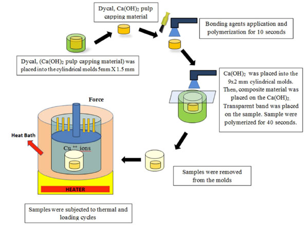
The illustration of the sample fabrication and diffusion process.
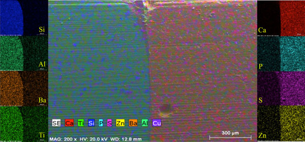
EDX dot mapping in the cross-section region of the sample.
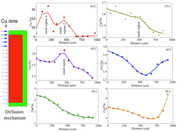
The temperature dependence Cu leakage into the sample obtained from EDX dot analysis in the connection region. The high Cu diffusion in (a) due to cracks and the left schema illustrate the diffusion of Cu ions in the designed sample.
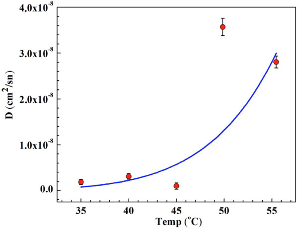
Temperature dependence of diffusion coefficient of the interface region of the samples.
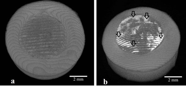
(a) 3D Micro-CT images of the unprocessed sample which the outer side is restorative material and the inner side is pulp capping material and (b) 3D Micro-CT images of the sample which exposed to copper. (image has white intense regions shown by the black arrow due to Cu treatment on the surface).
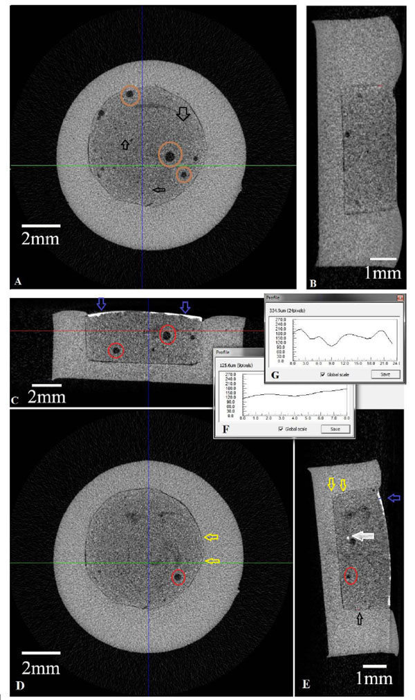
(A) Axial cross-secitonal view of the unprocessed sample (B) Sagital cross-sectional view of unprocessed sample (C) Coronal sectional view of Cu diffused sample (D) Axial cross-secitonal view of the Cu diffused sample (E) Sagital cross-sectional view of Cu diffused sample (F) Avarage pixel values of radio opacity of Cu diffused sample (G) Pixel value of depth of penetration of leaked Cu ions.
The prepared samples that removed from the molds were placed into the bottles containing 0.1 N Cu(NO3)2 then a 8 kg/cm2 load was applied to the sample. Each of the samples is incubated in water bath for the temperature range of 30 0C- 55 0C, with an increase of 5 0C by using Julabo 5 water bath for 12 hours. After thermal processing, microleakage investigations between the pulp capping material and the restorative material were analyzed by Micro CT (Micro Computed Tomography Model 1172) device. Then, in order to examine the micro leakage in cross section of the sample and the leak-induced diffusion mechanism, it was cut into two slices with IsoMet 1000 Precision Saw device. The surface morphology and elemental distribution analysis in the cross section area were analyzed by SEM, Leo Evo 40 VP and Bruker EDX unit combined by SEM system.
3. RESULTS AND DISCUSSION
We investigated the diffusion mechanism in the interface region of the fabricated samples by cutting the sample in the middle after Cu diffusion for different temperature for 12 h. Fig. (2) shows the Cu dot mapping analysis for the interface region of sample processed for different thermal treatments. As seen in the Fig. (2), some region dot intensities are higher than that of the other region which means the higher amount of Cu in the cross-section.
Cu concentration is higher in the region close to the surface of the material. It also appears that some regions during the interface section have higher dot intensity which is an evidence of the leakage between the pulp capping material and the restorative materials. Actually, we only investigated one cross-section of the sample (2D analysis), if we cut the sample into different slices, it will be seen that there are a number of Cu rich regions in the sample. So, the micro structural investigations in this study give us a road map for leakage mechanism between the restorative materials and pulp capping materials in dental science.
The Cu distribution of the sample processed at 30oC, have huge Cu content as seen in Fig. (3) which is not customary during the study. So, when we investigate the reason of high Cu content in the cross section of the sample, it was found that there is a big crack in the interface of the sample. This result has important conclusion for the leakage studies in the dental science. The improper application of dental treatments gives unusually big leakage and so, the patient suffers just after dental treatments.
In order to examine quantitatively the amount of diffused Cu ions, Cu content was determined by EDX dot analysis (Fig. 2) from surface to substructure of the interface region and we investigated the Cu leakage in the system. According to EDX dot analysis, it is clear that there was a definite leakage in the interface region of pulp capping and restorative materials. The cracks and holes which were formed during the dental treatment have energetically metastable regions and they easily cause an accumulation of Cu ions in these regions hence the Cu ions in these regions trigger the growing of holes and cracks. Furthermore, the thermal fluctuations due to consuming of hot and cold foods can cause the growing of the hole and crack regions. In this condition, the leaked materials inside the tooth reach the nerve region of tooth which causes pain to the patient. Furthermore, it can also cause the percolation, secondary decay, post-operative sensitivity and disappearing of aesthetics after staining.
The leakage mechanism between the restorative and pulp capping materials has great importance for the development of the ways to treat and determine the exact reason of pain after dental surgery and relief it. Fig. (3) shows the Cu concentration change with distance from surface to following regions of the samples depending on the thermal treatments. Basically, the expected change of Cu concentration with distance after diffusion should be in the form of exponential decrease curve from the surface and there should be an accumulation in the subsequent region of the interface regions. Although the obtained curve from EDX dot mapping analysis shows almost expected structure as mentioned above, some dots in the interface region have higher concentration than that of the other regions as seen in Fig. (3). This case is an evidence of the discussion given in previous section. So, the EDX dot mapping process for the determination of the leakage mechanism in the tooth study is a reliable method for this kind of studies. The obtained results demonstrate that Cu ions can easily diffuse to interface region and cause the deformation of the materials. The ionic radii of Cu ions are greater than the other elements such as C, B, H and N and it is important for human life. So, we concluded that the atoms or ions which are smaller radii can diffuse and easily reach the nerve inside the tooth.
According to Fig. (3), the concentration of Cu ions was increased by increasing the thermal treatment temperatures. The increase of the Cu content with temperature is expected. Because an increase in the temperature will increase the kinetic energy and the oscillation frequency of the atoms, so the mobility of the diffused atoms will increase then it can cause the increase of diffusion rate and concentrations.
Cu ions in the solution diffuse from regions of higher concentration to regions of lower one with heat treatment and time. Therefore, the percentage concentration of Cu ions in the material changed with increasing the heat treatment conditions such as temperature and time. If the concentration at some point changes with time, Fick’s second diffusion law can be used [22]. We assume that Cu=100% for x>+L and x<-L, Cu=0, for at t=0. When diffusion starts (t>0), the concentration of Cu in the designed material region changes with the time and temperature. A solution of the diffusion equation in this case can be obtained in the following manner: Imagine that the diffused region for Cu ions consists of n slices. If ai is the distance from the center of the i th slice to x=0, When n →∞ and Äai →0, The solution of this approach is the form of error function as given below;
Diffusion coefficients for Cu ions were calculated by substituting of the obtained concentration values. The calculated diffusion coefficients are presented in Fig. (4) depending on heat treatment conditions. It is found that the diffusion coefficient increases with the increasing temperature and this is due to thermal fluctuations and vibrations of ions in the samples.
3D top-view micro-CT images of samples unprocessed and processed by Cu were given in Fig. (5a and b), respectively. It is obvious that the unprocessed sample has two different regions in Fig. (5a) where the outer side is restorative material and the inner side is pulp capping material as mentioned SEM, EDX section. The Micro-CT images have white intense regions due to Cu treatment on the surface section of inner part of the sample designed as seen in Fig. (5b), the outer part has no clue about Cu aggregation. So we concluded that pulp capping material has an ability to accumulate of diffuse materials. This result will lead to new studies for the modification of pulp capping materials.
Different cross-sectional views of the unprocessed and Cu diffused samples obtained by Micro-CT analysis, are given in Fig. (6A-E). In the axial section of the unprocessed sample, it is found to be any radio-opacity between pulp capping material and restorative materials. On the other hand, there are porosities inside the sample and the radio opacity in the joining region of the pulp capping and restorative materials should be due to Zn ions of pulp capping material as seen in Fig. (6a). Similar observation was also obtained in the sagittal section of unprocessed sample as seen in Fig. (6b).
The dense accumulation of Cu was observed especially the surface of pulp capping materials as the cross-section of the Cu processed sample is seem in Fig. (6C). The yellow arrows in the Figs. (5D and E) indicate the radio-opac regions in the processed sample which are a good example of the diffusion of Cu ions inside the sample. The red circle shows the holes (Porosity regions) formed during the sample fabrications and the white arrows show the holes (Porosity regions) which have high Cu concentration among them, Fig. (6E). So, we predicted that the porosity regions have high potential for Cu accumulation inside it because of the holes and crack regions have higher free energy than the other region of the materials and the diffused elements can easily accumulate in these regions. Meanwhile, avarage pixel values of radio opacity of Cu diffused sample are shown in the Fig. (6F) and pixel values of depth of penetration of leaked Cu ions are shown in Fig. (6G).
The hole radii in the samples observed by MicroCT were measured for the unprocessed and Cu diffused samples and it was found that the radii of holes increased with Cu diffusion which indicates the settlement of Cu ions in these regions. This result is important for the leakage studies since the leakage time depends on the diffusion of elements.
In the leakage studies, it is well known that there is no remarkable effect by adhesion resin and the type of pulp capping and restorative materials can cause the leakage mechanism. As a result, it is obvious that the diffusion rate and so micro-CT images will change by the sample to sample and also preparation conditions, but our principal goal is to show that the leakage studies in dental research by Cu diffusion method are much reliable and cheaper method than the others such as Ag leakage studies.
CONCLUSION
In this study, we presented the microstructure and mechanism of the diffusion and leakage between restorative and pulp capping material by using Cu solution. It is concluded that Cu ions can be used for the leakage or diffusion studies in dental research since Cu ions have different advantages as mentioned before such as the price and abundance in the planet. The diffusion calculations showed that leakage is increased for hot environment and the regions which havecracks and holes occured during the dental treatment or after dental treatment. Furthermore using Cu solution for diffusion in dentine is an effective and easy method, it is necessary to carry out further studies by using Cu ions in the leakage studies.
CONFLICT OF INTEREST
The authors confirm that this article content has no conflict of interest.
ACKNOWLEDGEMENTS
This study was supported by the Inonu University research council under contract number 2013-74.
ETHICAL APPROVAL
This study does not need the ethical approval because we didn’t use any living organism during the experiments.