All published articles of this journal are available on ScienceDirect.

The Effect of Preparation Design on Stress Distribution in Lithium Disilicate Laminate Veneer using 3D Finite Element Analysis.
Abstract
Background:
A layer of ceramic bonded to the facial surfaces of prepared teeth to create a ceramic esthetic veneer, also known as a laminate veneer.
Objective:
This study aimed to examine the effect of preparation design on the stress distribution in lithium disilicate veneer at different angulations of masticatory loading.
Methods:
The finite element approach assessed the structure stress distribution. So, Exocad dental CAD was used to obtain the models, which consist of an upper central incisor in three dimensions (3D), and prepare them with the same software for an indirect veneer. The models were imported into software (SolidWorks; Dassault Systems) to construct solid models. The external load used in this study was 100 N at 60 degrees (intercuspal) and 125 degrees (protrusive) in the palatal surface, two mm below the incisal edge. The models were restored using e-max laminate veneers with different tooth preparation designs (palatal chamfer and window preparation designs). Analysis and calculations were performed on the stress distributions and maximum stress values of the tooth structures, cement layer, and laminate veneer.
Results:
With a window preparation design, the maximum stress values in the tooth and laminate veneer were higher. In the palatal chamfer design, stresses were dispersed more consistently through the cement layer and laminate veneer. Higher stress was generated by protrusive movement than by intercuspal movement.
Conclusion:
Compared to window preparation, the palatal chamfer design for lithium disilicate laminate veneer showed a more favourable stress distribution. Regardless of the preparation design, maximum stress values were observed in the cervical and incisor areas of the tooth structure.
1. INTRODUCTION
A ceramic layer is bound to the facial surfaces of prepared teeth to create a ceramic esthetic veneer, also known as a laminate veneer. Ceramic laminate veneers are produced specifically for each patient and are created in a dental lab. Most ceramic laminate veneers are made by machining or heat-pressing lithium disilicate or leucite-reinforced ceramic [1].
The principle of conservative dentistry with less invasive procedures involved ceramic laminate veneer preparations. Furthermore, this method has been effectively applied to correct flaws, such as diastema, minor fractures, and stains and improve patients' aesthetic conditions [2, 3].
Various tooth preparation geometries for ceramic laminate veneers are described in the literature. Two of them are used in this study because they offer more benefits. These are (1) the “window preparation,” which involves minimal preparation of the labial surface and doesn't involve the incisal edge; and (2) the “palatal chamfer preparation,” which involves labial surface preparation with incisal edge reduction. The durability of ceramic veneers is not primarily determined by the materials used. Previous studies have demonstrated that the preparation design impacts the ultimate result [4, 5]. Even though a rounded shoulder or chamfer has been proven to be the best marginal design for obtaining an obvious finish line and suitable structural resistance, more approval must be given regarding the potential lingual extension of the veneer preparations [6, 7].
Since practically all of the information about the clinical attitude of these restorations was based on personal records, the effect of various tooth preparation geometries on the fracture strength and stress distribution of laminate veneers is still controversial [8, 9].
The several events in the examined models can be better understood by finite element analysis (FEA), a non-destructive test connected to in vitro tests. The finite element method enables a more exact system behaviour to check by better reviewing the stress distribution within the materials or at an interface. Every element's mechanical property can be written as a function of node translation. When such nodes are loaded in specific ways, the model operates similarly to the structure it represents [10-12].
So, the study's objective in vitro is to examine the effects of tooth preparation designs on the stress distributions in lithium disilicate veneer at different angulations of masticatory force loading (60 and 125 degrees). The null hypothesis is that there is no difference in stress distribution between the window preparation design and the palatal chamfer design.
2. MATERIALS AND METHODS
The model consisting of maxillary central incisors was obtained from Exocad dental CAD (Exocad GnbH, Germany) and prepared by the same software (Exocad dental CAD) with the protocol for clinical preparation:
• 1 mm interproximal reduction.
• The cervical border is 1 mm coronal to the cement-enamel junction (CEJ).
• 0.7 mm reduction of the buccal aspect for palatal chamfer preparation (extension two mm toward the palatal aspect to cover the incisal edge with the chamfer finish line).
• 0.7 mm reduction of the buccal aspect for window preparation.
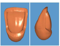
Finally, two digitally prepared tooth models were obtained (Fig. 1).
The ceramic veneer (IPS e-max Press, Ivoclar Vivdent, Schaan, Liechtenstein) with a thickness of 0.5mm and a cement layer of 0.2mm (RelyX™, 3MESPE, USA), according to manufacture instructions, was designed on the digitally prepared tooth using Exocad dental CAD (Exocad GnbH, Germany) [13]. The models consist of four main volumes: the enamel, the dentin, the cement, and the veneer structures. The models were imported into software (SolidWorks; Dassault Systems) to construct solid models. Four models have been obtained, as reported in Table 1. The models didn't include roots, PDL, or bone. The mesh is formed by a mix of tetrahedral, linear triangular, and linear quadrilateral elements (243309 elements and 314365 nodes), and the solids are considered isotropic, linearly elastic, and homogenous. The mechanical properties used in this study are elastic modulus and Poisson's ratio for laminate veneer, cement layer, enamel, and dentin.

| Model No. | Preparation Technique | Load Applications | |
|---|---|---|---|
| Mod. 1 | Window | 60° | |
| Mod. 2 | Palatal chamfer | 60° | |
| Mod. 3 | Window | 125° | |
| Mod. 4 | Palatal chamfer | 125° | |
Regarding the laminate veneer and cement layer, the mechanical properties (elastic modulus and Poisson's ratio) of a disilicate lithium ceramic (IPS e-max press, Ivoclar Vivadent, Schaan, Liechtenstein) and a methacrylate resin-based luting agent (RelyX™ Veneer Cement, 3M ESPE, USA) were taken into account. The mechanical properties of the isotropic materials are described in Table 2. The external load used in this study was 100 N at 60 degrees (intercuspal) and 125 degrees (protrusive) on the palatal surface, two mm below the incisal edge. The load was applied separately to selected fixed nodes for all models.
2.1. Experimental Test
The finite element solution of each model was carried out using a three-dimensional planar strain model and the Abaqus/19 package. A structural linear static analysis assessed the stress distribution in important areas. Maximum principal stress was used to analyze the stress distribution in tooth structure, cement, and veneer.
3. RESULTS
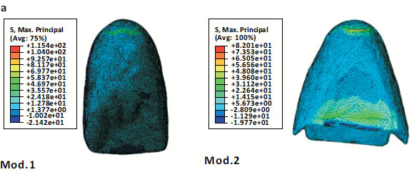
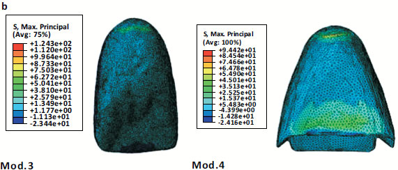
There are two fundamental finite element models. Table 3 reports the maximum principal stress that was recorded. Maximum stress areas are reported in Table 4. The stress distributions in laminate veneer under intercuspal load for Mod. 1 and Mod. 2 are compared (Fig. 2a). The stress in the veneer was uniformly distributed in both models. The maximum stress value in Mod. 1 was 200 MPa in the cervical area, while in Mod. 2, the maximum value reached was 148 MPa in the incisal region. In Fig. (2b), the stress distributions in laminate veneer under protrusive load are marked (Mod. 3 and Mod. 4). The maximum value that occurred in Mod. 3 was 236 MPa. In Mod. 3, the stress concentrated in the cervical area and progressively decreased in the buccal area. In Mod. 4, maximum concentration stress (196 MPa) occurred in the incisal region and gradually decreased in the cervical region.
| Model No. | Laminate Veneer (MPa) |
Cement Layer (MPa) |
Tooth Structure (MPa) |
|---|---|---|---|
| Mod. 1 | 200 | 25 | 115 |
| Mod. 2 | 148 | 11.5 | 82 |
| Mod. 3 | 236 | 32.8 | 124 |
| Mod. 4 | 196 | 15 | 94 |
| Models No. | Max. Stress Area | ||
|---|---|---|---|
| Veneer | Cement | Tooth Structure | |
| Mod. 1 | Cervical area | Incisal area | Cervical area |
| Mod. 2 | Incisal area | Buccal surface | Cervical, incisal area |
| Mod. 3 | Cervical area | Incisal area | Cervical area |
| Mod. 4 | Incisal area | Buccal surface | Cervical, incisal area |
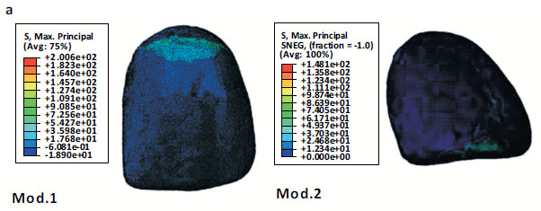
Mod.2: stress distribution in laminate veneer under tearing load with palatal chamfer preparation.
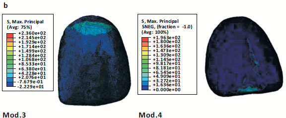
Mod.4: stress distribution in laminate veneer under protrusive load with palatal chamfer preparation.
The stress distribution in the cement layer under intercuspal movement in Mod. 1 and Mod. 2 was compared (Fig. 3a). The maximum stress value that occurred in Mod. 1 was 25 MPa. In Mod2, the maximum stress value recorded was 11.5 MPa. In Mod. 2, the stress was focused on the buccal and incisal areas. In Fig. (3b), the stress distribution in the cement layer under the protrusive load was marked (Mod. 3 and Mod. 4). In Mod. 3, the stress reached a maximum value of 32.8 MPa, and the stress was concentrated in the cervical and incisal areas. In Mod. 4, the maximum stress value was 15 MPa. The high stress was concentrated in the buccal and incisal areas in Mod. 4.
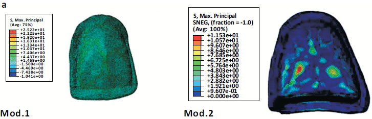
Mod.2: stress distribution in cement layer under tearing load with palatal chamfer preparation.
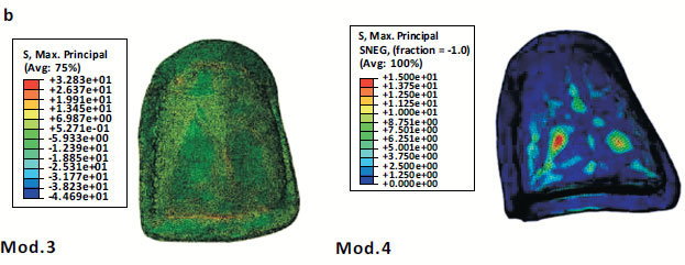
Mod.4: stress distribution in cement layer under protrusive load with palatal chamfer preparation.
Mod.2: stress distribution in tooth structure(lingual surface) under tearing load with palatal chamfer preparation.
Mod.4: stress distribution in tooth structure(lingual surface) under protrusive load with palatal chamfer preparation.
In Fig. (4a), the stress distributions in dental tissue under intercuspal load were marked (Mod. 1 and Mod. 2). In Mod. 1, the stress in the incisal region was decreased. The maximum stress value (115 MPa) was recorded in the cervical area of the palatal aspect. In Mod. 2, the maximum stress value was 82 MPa. Stress was concentrated in the cervical and incisal areas of the palatal aspect in Mod. 2. In Fig. (4b), reports the stress distributions under protrusive movement in tooth structure (Mod. 3 and Mod. 4). In Mod. 3, the higher stress (124 MPa) is recorded in the cervical area of the palatal aspect and reduced in the incisal area of dental tissue. In Mod. 4, the maximum stress value (94 MPa) was recorded in the cervical and incisal areas of the palatal aspect.
4. DISCUSSION
Finite element analysis was used in this study to monitor and analyze stress distribution. It is often regarded as the most accurate method because it allows researchers to quantitatively assess complicated biological systems for which other approaches are impractical or unsolvable [16-18].
A mathematical representation of a real object or phenomenon is a numerical model, such as one that uses FEM technology. The fact that a mathematical model is virtual—that is, it resides in a computer and is entirely programm- able—gives it significant advantages over in-vivo testing. The investigator can easily change the test parameters, model parameters, and geometries. Additionally, the investigator can copy any preferred result and reiterate the test (simulation) anytime. All of these things are not achievable during in vivo studies. Consequently, a well-validated mathematical model gives the investigator an extremely potent tool for analysis [19, 20].
The likelihood of fluctuation in the results due to sampling error is eliminated since numerical values obtained from stress analysis are mathematical calculations without variance and because variables can be changed with computer precision. Any number of times the same FEM analysis was repeated, it would always produce the same results. As a result, it is evident that outcomes are never the result of chance events but rather are the result of variable control. Because of this, a conclusion from a FEM study is typically reached without using formal inferential statistical analysis [21, 22].
The result of this study reveals that the window preparation technique develops higher stress than the palatal chamfer preparation in both 125° (protrusive) and 60° (intercuspal) load conditions (Figs. 2-4), and this is agreed with by Zarone et al. in 2005 [23]. Such evidence appears to be due to the load direction. When a tooth is subjected to therapeutic veneer treatment, the first substrate located by the load direction is enamel, which performs similarly regardless of the ceramic and cement agent, reflecting similar results for dentin between all groups. This result can be clarified because the thickness of the remaining dentin is the same for each group and close enough to the load to prevent variations in behaviour groups. The maximum principal stress result demonstrated that, regardless of the restorative material or occlusal condition, the palatal chamfer design reduces stress in both the tooth structure and the laminate veneer, as seen in other investigations [23, 24]. (Table 3).
Regarding loading circumstances, performing window preparation makes the intercuspal and protrusive movements more stressful (Figs. 2-4). While in palatal chamfer preparation, the opposite situation was noticed. In this study, most of the tooth structure can evenly transport the load from the tooth to the cement layer and then to the veneer because the tooth structure is subject to compressive force.
The e-max veneer is a barrier during functional motions by absorbing most stress and preserving underlying dental tissue according to the stress variance between the veneer and tooth structure (Table 3). All models saw larger stress concentrations at the veneer structure level. This phenomenon can be explained by the therapeutic system's overall mechanical behaviour. The e-max veneer has a higher elastic modulus than the cement and tooth structure. Since the prepared tooth's weakest link is the incisal and cervical regions, high stress is concentrated in these areas. The cement layer was a crucial area for biomechanical behaviour [25]. The outcome demonstrated that the material with a lower modulus of elasticity (less stiffness) produces less concentration stress, as reported by other evidence [26]. The cement layer, however, served as a stress absorber (Fig. 3).
Considering the three layers of the examined restorative system (tooth structure, cement layer, and laminate veneer), when utilizing window preparation, the stress was consistently localized at the cervical level (Figs. 2-4). When employing palatal chamfer preparation, the stress was dispersed from the cervical area of the palatal aspect to the area of load application in the middle region of the incisal area. The stress within the veneer and tooth structure decreases as the preparation depth increases. Prior 3D-FEA research claimed that stress was localized in the incisal area [27, 28]. Nevertheless, this study also found the stress concentrated in the cervical area of the palatal surface, which Tsoukindas A. et al. had previously reported on in 2020 [29].
The volume of restoration would be increased by eliminating contact points proximally, typically done in patients with significant discolouration or deformity. In the current investigation, the window preparation and palatal chamfer designs, intended to create a good finish line on the proximal surface, failed to preserve contact points proximally. Castelnuovo et al. showed that the strength of the palatal chamfer design is lower than that of the butt joint design because of the thickness of the ceramic [8]. Based on the current findings, the palatal chamfer preparation design may be a better alternative for laminate veneer since it has a lower maximum main stress and a more consistent stress distribution in the cement layer. This study shows a significant difference in stress distribution between the window and palatal chamfer designs, so the null hypothesis was rejected.
The FEA, as a computational technique, did not take into account all aspects of the oral environment, such as the anisotropic nature of dentin and the nonlinear viscoelastic properties of the periodontal ligament, which both required a significant amount of experimental data. Other limitations include that the mean masticatory load in the anterior region could vary from 93 N to 206 N depending on age, race, gender, tooth loss, TMJ condition and pain, periodontal support of teeth, weight, and height [30-32].
CONCLUSION
Concerning different loading angles, the window and palatal chamfer designs varied mechanically within the confines of the current investigation. Compared to window preparation, the palatal chamfer design for lithium disilicate laminate veneer showed a more favourable stress distribution. Regardless of the preparation design, maximum stress values were observed in the cervical and incisor areas of the tooth structure.
LIST OF ABBREVIATIONS
| % | = Percentage |
| 2D | = Two Dimensional |
| 3D | = Three Dimensional |
| CAD | = Computer Aid Design |
| e.g | = For example |
| FEA | = Finite Element Analysis |
| FEM | = Finite Element Method |
| Fig | = Figure |
| GPa | = Gigapascal |
| Max | = Maximum |
| MM | = Millimeter |
| MPa | = Megapascal |
| Mod | = Model |
| N | = Newton |
| USA | = United State America |
| Tab | = Table |
HUMAN AND ANIMAL RIGHTS
No human and animals were used for the studies that are the basis of this research.
AVAILABILITY OF DATA AND MATERIAL
All the data and supporting information is provided within the article.
ACKNOWLEDGMENTS
Declared none.