All published articles of this journal are available on ScienceDirect.

Applications of Finite Element in Implant Dentistry and Oral Rehabilitation
Abstract
Finite element is widely applied in dentistry to study the stress distributions on adjoining bone, the biomechanics of dental implant and bone; implant and bone interface and study its fatigue behaviors of the implant. This article presents various applications of finite element in implant dentistry. Available articles were searched and reviewed from March 1980 till September 2020 from Pubmed, Scopus, Google Scholar, and Science direct. Relevant studies were included and critically analyzed. Finite element is an important tool in implant dentistry to study the stress distributions on adjoining bone, the biomechanics of dental implant and bone; implant and bone interface, and fatigue behaviors.
1. INTRODUCTION
Currently, the dental implant is integrated as a routine dental treatment for the restoration of teeth, oral rehabilitation, aid in the retention, and support for the prostheses [1-3]. The dental implants present over 95% of the success rate if designed, manufactured, and inserted correctly [4]. In addition, the aid of digital technologies has enhanced the success [5]. Implants are anticipated to present their function lifelong.
Various factors influence the success of dental implants [6]. Insertion technique, surgical techniques, and clinical skills also play a vital role in the osseointegration of the dental implant. Stress of implant, jawbone, and the interactions of their biomechanical behavior establish the dental implant’s success [7].
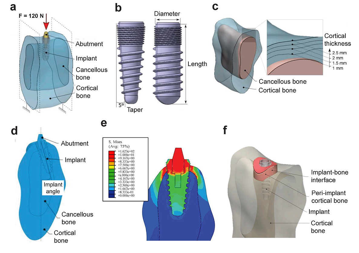
A 3D finite element can help study the biomechanics of dental implants on the bone; stress distributions on surrounding bone, implant-bone interface, study the fatigue behaviors of implant, etc [6-9]. as shown in (Fig. 1) [8]. Various mechanical properties of important body parts and biomaterials used for the FE modeling are shown in Tables 1 and 2, respectively.
The mechanical properties of common biomaterials in implant dentistry for FE modeling are shown in Table 2. It showed a variation of Young’s modulus of elasticity and Poisson ratio among various biomaterials.
| Materials | Mechanical Properties | Value | Study | |
|---|---|---|---|---|
| Bone | Cortical bone | Young modulus, E (GPa) | 13.7 | [10, 11] |
| Poissons ratio, ʋ | 0.3 | [10, 11] | ||
| Cancellous bone (D1, D2, D3) | Young modulus, E (GPa) | 1.37 | [10, 11] | |
| Poisson ratio, ʋ | 0.3 | [10, 11] | ||
| Trabecular bone (D4) | Young modulus, E (GPa) | 1.1 | [10] | |
| Poisson ratio, ʋ | 0.3 | [10, 12] | ||
| Teeth | Enamel | Young modulus, E (GPa) | 82500 | [13] |
| Poisson’s ratio, ʋ | 0.33 | [13, 14] | ||
| Dentin | Young modulus, E (GPa) | 18600 | [11, 15] | |
| Poisson ratio, ʋ | 0.31 | [11, 12, 15] | ||
| Materials | Mechanical Properties | Value | Study | |
|---|---|---|---|---|
| Ti Implant | Abutment materials, Prosthetic Teeth | Young modulus, E (GPa) | 113.8 | [10] |
| Poisson ratio, ʋ | 0.34 | [10] | ||
| Co-Cr | Crown framework materials | Young modulus, E (GPa) | 218 | [10] |
| Poisson ratio, ʋ | 0.33 | [10] | ||
| Porcelain | Prosthetic superstructures | Young modulus, E (GPa) | 218 | [10] |
| Poisson ratio, ʋ | 0.35 | [10] | ||
2. MECHANICAL PROPERTIES OF BONE, TEETH BIOMATERIALS FOR FINITE ELEMENT MODELING
There is a variation of Young’s modulus and Poisson ratio between enamel and dentin, and cortical, cancellous, and trabecular bone. Various mechanical properties of important body parts are shown in Table 1.
An example of finite element model is shown in Fig. (2) and it consists of the cortical, cancellous bone an implant and abutment [16]. The model is designed from a numerical strategy from the assembly of the different parts together and the stress distribution is studied.
3. APPLICATION OF FINITE ELEMENT MODELING IN IMPLANT DENTISTRY
3.1. Percentage of Osseointegration
Osseointegration of implant after placement determines the high success and survival rate of dental implants. Bone resorption and loss of the implant may be occurred because of stress around the implants. Lai et al. [17] studied the percentage of osseointegration using a FE model which was designed from the dental computed tomography. They used 3.75 x 10-mm cylindric implant in an edentulous mandible. Using a load of 35 N on the restoration at the vertical axis of the implant, the maximum principal stress, minimum principal stress, and Von Mises stress were calculated. They found that the maximum stress was distributed at the implant’s neck within the bone. The stress at the implant-tissue interface showed an inverse function to the osseointegration percentage.
3.2. Fatigue Behavior of Dental Implants
The fatigue behaviors of implant influence the stress surrounding bones. Chen et al. [18] investigated the stress at implant and interface of bone, and fatigue behaviors of Ti implant under two different loading; dynamic and static using a 3D finite element model of a mandible segment with an implant bone was constructed by CAD software. It showed that the stress present in the cortical bone was 17.15% higher under the dynamic loading than the static loading. The implant and interface at bone showed less stress than the yield strength of Ti. They concluded that the implants could transfer stress from the implant and bone interface to the bone (cancellous) and root region. The improvement in design configuration is safe under normal loading.
Finger amputation may result in unesthetic and function problems, which can be restored with a finger prosthesis. Amornvit et al. [19] evaluated the stress distributions around implant-retained finger prosthesis under a vertical force on the implant (4.5 mm diameter and 14 mm length) with a force of 50 N. The greatest stress was found at the abutment screw, whereas the least stress was found around the apical third. Hence, there should be a suitable biomechanical configuration to achieve the long-term success of the implant.
3.3. Sinus Lift Surgery
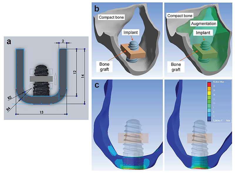
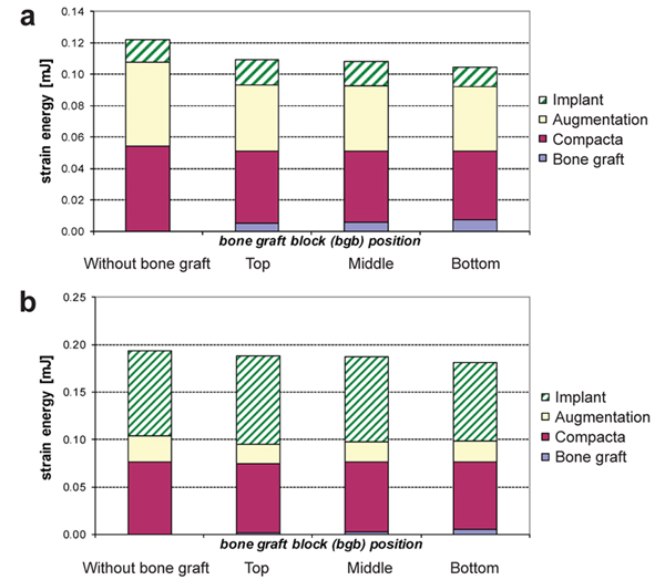
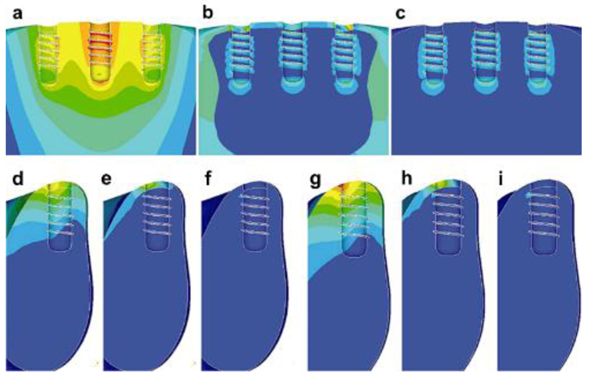
The amount and quality of the bone play a vital role in the successful rehabilitation of edentulous maxilla using implants. An inadequate bone may be caused due to various reasons resulting in bone resorption [20, 21]. Sinus lift is used commonly in bone thickness is below 2-3 mm and the patient requires bone augmentation procedures [20, 22]. Indirect sinus lift has also shown good survival rates [22-24]. Schuller-Götzburg et al. [20] evaluated sinus lift augmentation after adding block bone graft using a FE model of the maxillary molar region (Fig. 3). The stress distribution was calculated at 3 positions: at contact with the sinus floor, middle of the implant helix, and upper third of the implant. The stress for masticatory force (Fz) were 3 times lesser compared to the protrusion load (Py) (Fig. 3c). The maximum stresses occurred in the lower part of compact bone. Hence, placing the bone graft at the lower region has less strain density for the implant (Fig. 4).
4. FACTORS AFFECTING THE STRESS DISTRIBUTION AROUND IMPLANT
The loading on dental implants is suggested only after the adequate stability of the implant and no excessive loads should be applied. The implant diameter, length, loading angle, and insertion depth has an effect on the stress distribution [8, 25]. Didier et al. [16] investigated the several parameters (implant diameter, length, angle of inclination, taper, Young’s modulus, the thickness of the cortical bone, and Young’s modulus of the cancellous bone) on stress distribution and load transfer between the dental implant and bone using a FE model. They found that the implant diameter and Young’s modulus and the cortical thickness were the most influential parameters on the two responses.
Savadi et al. [26] studied the effect of implant surface topography and loading conditions on stress distribution using 100 (axial force) and 50 N loads (non-axial force). They found that the smooth-surfaced implant showed high punching stress at the apex of the implant. The porous-coated porous surface topography shows a more uniform distribution of stress. In another study, a surface coating of graphene oxide on the Ti implant was studied and found that they showed better mechanical behavior than graphene [27]. Recently, it has been found that graphene, graphene oxide (GO), and reduced Graphene Oxide (rGO) a potential application for coatings on titanium alloys [28-31]. More clinical trials are required to validate the findings of the present study [27].
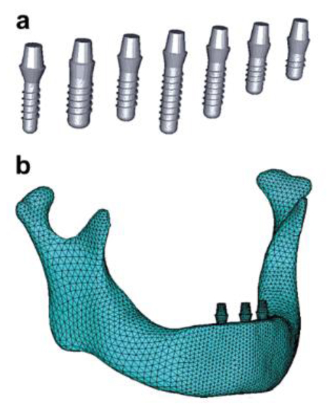
Fiorillo et al. [32] found that the results on this new type of connection and on all the implant components are satisfactory; the distribution of forces (800 N) was optimal on the peri-implant tissues. Ding et al. [8] studied the role of the implant length and implant diameter on the stress distribution in the mandible around dental implants design after using a FE model from CT using a load of 150 N (Fig. 5). They used seven Straumann implant design of implant length (6 - 14 mm) and implant diameter (3.3 - 4.8 mm). It showed that the oblique force compared to the vertical force resulted in excessive stresses and strains on the implant and the bone. Hence, increasing the diameter and length of the implant decreases the stress and strain on the bone. The diameter affects more to relieve the stress and strain compared to the length. Similarly, Ding et al. [33] also mentioned that an increasing implant diameter significantly decreases the stress and strain on the implant and bone interfaces where they experimented in three mandible models. It also showed that the implants with a length of 10 mm should be at least 4.1 mm in diameter to result in less stress on the bone. In addition, oblique forces to implants must be minimized or avoided.
Another study investigated the role of dental implant diameter, loading angle, and insertion depth on stress and strain in a jawbone using the FE study [25]. Application of the maximum load of 200 N in various loading angles (0 to 85 degrees) buccolingually, they found that the maximum stress was at the cortical bone on the lingual side adjacent to the implant. Larger diameter implant and increased insertion depth substantially improved the stress/strain distribution. Implant loaded at an oblique loading angle in a shallow insertion depth is most harmful to bone and implant. Hence, an enhanced implant neck design and an adequate depth implant are favorable for the bone in implant/bone systems.
De Moraes et al. [34] studied the diameter, implant loading, and type of the connection on stress patterns in the bone with an increased crown-implant ratio. They applied an axial force (200 N) or oblique force (100 N) on the dental implant with 8.5 mm length, diameter 3.75 or 5 mm, and various connection types; internal hexagon external hexagon, and Morse taper using posterior mandibular region 3D models with the InVesalius, Rhinoceros 3D 4.0 and SolidWorks 2011 software programs. Models were processed using the Femap 11.2 and NeiNastran 11.0 programs. It was found that the angled compared to axial loading showed high stress in the cortical bone. They found that with the application of oblique force, the stress was high in the cortical bone compared to the axial force. Wider diameter implants showed favorable stress distribution irrespective of the type of connection. In addition, Morse taper implants presented the favorable distribution of the stress, especially in the oblique loading.
The short implants may be considered if sufficient bone height is not present mandibular arch [35-37]. Vidya Bhat et al. [35] evaluated the influence of implant lengths (6, 8, 10, and 13 mm) on stress in the mandibular arch using a FE model by applying a static vertical force (250 N) and a horizontal force (100 N). The baseline demographic variables, including age, gender and smoking status, bone quality, location, implant dimensions, and types of prostheses, were compared to ensure balance among groups. They found that under the vertical load, the short implants were able to tolerate loads and disseminate reduced load to the bone. Bruxing forces must be minimized by increasing the number and diameter of the implants [37].
5. LIMITATIONS OF FE STUDIES IN IMPLANT DENTISTRY
Although the FE method is a precise method for analyzing structures, they have certain limitations [19, 35, 38]:
- The implant and bone interface is predicted as a continuous bond.
- No micro-movement at the implant and bone interface during loading which is different from the real clinical situation.
- Osseointegration is expected 100%, which is ideal and never true in the clinical situation.
- The bone (cortical, cancellous) and implant are taken as isotropic and homogenous but in real the bone is anisotropic and inhomogeneous.
- The implant is rigidly anchored in the bone.
- The loads were applied only at point locations.
- The force applied duration in the implants and oral cavity differs.
Furthermore, in most FE studies, generally, only a single loading point and angle are tested rather than an episode of stress as in clinical situation [39]. Hence the FE studies lack the fatigue, aging, thermal, and continuous mechanical cyclic loading when analyzing the prosthetic dental implant. In many finite element studies, they use optimal force. Further studies should be done considering all these factors.
CONCLUSION
Finite element is an important tool in implant dentistry to study the stress distributions on adjoining bone, the biomechanics of dental implant and bone; implant and bone interface and study the fatigue behaviors of the implant. It has been shown that a wide diameter and longer implant provide suitable stress distribution in the bone. Morse taper implants show less stress. Future innovations would be creating a micro-movement at the implant and bone interface during loading to simulate the real clinical situation.
CONSENT FOR PUBLICATION
Not applicable.
FUNDING
None.
CONFLICT OF INTEREST
The authors declare no conflict of interest, financial or otherwise.
ACKNOWLEDGEMENTS
Declared none.