All published articles of this journal are available on ScienceDirect.
Influence of Implant Design (Cylindrical and Conical) in the Load Transfer Surrounding Long (13mm) and Short (7mm) Length Implants: A Photoelastic Analysis
Abstract
Purpose:
This study compared the influence of implant design (cylindrical and conical) in the load transfer on bone surrounding 13mm and 7mm length implants under simulated occlusal loading, using photoelastic analysis.
Method:
Dental implants of 4mm diameter were divided into four groups, which varied in length and design: Group 1- standard (13 mm) cylindrical implant; Group 2 - standard conical implant; Group 3 – short (7 mm) cylindrical implant, and Group 4 - short conical implant. After the inclusion of the implant models in a photoelastic resin, they were subjected to a static load of 100 N. The lengths of the fringes that were generated were measured in three portions since the implants body: crestal, central and apical portion, parallel to the implant long axis. Furthermore, the entire extension area of dissipation of force was measured. Data were analyzed by one-way ANOVA (α = 0.05).
Results:
Lower stress was observed at the crestal bone in groups 2 and 4, while the stress levels in groups 1 and 3 were higher with significant differences compared to the other groups (p<0.05).
Conclusion:
The total amount of stress transmitted to the bone was not affected by implant length under axial loading condition, but changed in relation to the implant design with respect to the concentration of the fringes, which corresponded to the load distribution, with even more dissipation by conical implants.
INTRODUCTION
Alveolar bone atrophy is considered one of the main factors affecting the placement of dental implants with the aim of achieving adequate restoration [1-3]. The presence of insufficient bone volume may require the adoption of bone grafting procedures in order to increase the available bone [4]. Commonly, bone graft materials are used to increase the posterior volume of the pneumatized maxillary sinus via lateral or crestal sinus floor augmentation [5-7]. In atrophic mandibles, bone volume in the posterior areas is often not sufficient to allow implant placement, due to the presence of the inferior alveolar nerve which must be preserved. Vertical bone augmentation in atrophic mandibles has been previously described in the literature [8, 9], however, there is a lack of consensus about which is the best or most predicable surgical protocol. Moreover, most bone grafting procedures present complications and adverse sequelae, which might jeopardize the postoperative period and affect the success of the procedures themselves [4, 10].
Short implants (less or equal than 8 mm long) were introduced in clinical practice to obviate the need of bone grafting procedures in sites with reduced bone volume [11]. Clinical outcomes of the use of short implants were evaluated in several systematic reviews of the literature [5, 12, 13]. The success and survival rates of such restorations were comparable with those reported in the previous studies on standard length implants although the follow-up time for short implants is slightly shorter than for longer implants [5, 12, 13].
Despite consideration of the adequate clinical performance of short implants, the stress distribution to the surrounding bone when a masticatory load is applied should be considered in predicting the success in long-term. Many implant designs have been introduced to optimize bone and soft tissue conditions under occlusal load that consists of applied axial and oblique direction of compression, tension, and torque. These macroscopic geometric characteristics have helped to distribute applied forces along the implant-tissue interferences [14]. Major stresses occur around implants during mastication. If these stresses increase to higher levels they may lead to bone resorption [15]. To prevent complications like this, it is necessary to understand where the maximum stresses occur during mastication, around the implants [16].
Finite element simulations were used to describe the characteristics of stress distribution on surrounding bone when a load was applied to simulated short implants [17, 18]. Other simulations can be used to analyze the biomechanical performances of an implant. Photoelastic simulations have the advantage of presenting situations more similar to reality compared to computerized ones [19-21].
Therefore, the aim of the present study was to assess, using photoelastic evaluation, the stress distribution patterns on single short implants compared to a standard length fixture with different designs (cylindrical and conical).
MATERIALS AND METHODOLOGY
Sample Preparation and Characteristics
Photoelastic models were generated from Araldite GY 279 photoelastic resin (Huntsman, Everberg, Germany), according to the manufacturer’s instructions for polymerization. Models were 45 mm high, 45 mm wide and 25 mm deep. To minimize the stress due to implant insertion, the fixtures were incorporated during polymerization. The stress due to the presence of the implant in the model was confirmed using a circular polariscope.
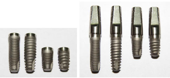
Two different implant designs (conical and cylindrical) with the same implant surface topography (Implacil De Bortoli, São Paulo, SP, Brazil) were compared in this investigation: standard cylindrical implant (group 1); standard conical implant (group 2); short cylindrical implant (group 3); and short conical implant (group 4). The length of the standard and short implants was 13 mm and 7 mm, respectively, with all implants being 4 mm in diameter (Fig. 1). A titanium straight prosthetic abutment was placed on each implant, with a torque of 30 Ncm, according to the manufacturer’s instructions.
The modelling and the experimental setting were set on the basis of the conditions described in the previously published papers [21, 33].
The models were subjected to a simulated occlusal axial load of 100 N. The value was chosen in accordance to other studies published before [21, 33]. The measure of the force of each loading pressure was confirmed using a calibrated load cell (low-range transducing cell, Model T51P, Ohaus Corporation, Pine Brook, NJ, USA), which was mounted on the base of the loading structure.
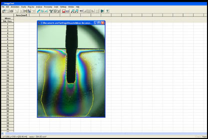
The area and the distance among the lines, that could be distinguished by color changes, generated in the resin after loading were evaluated by a computerized analysis (Image Tool 5.02 for Microsoft Windows™) of two high-resolution images (photographs) obtained from the front of the block of resin (Fig. 2). To measure the distance of the fringes from the implant body, three reference points were considered: the initial portion of the implant (p1), in the center of the implant (p2) and, in the most apical portion of the implant (p3), as shown in Fig. (3).

The measurements were taken independently by two researchers (SG and SC) and the measurements were repeated three times for each reference point for each group. The mean values were considered in the evaluation.
Statistical Analysis
Data of the measurements of the fringes area were analyzed by one-way ANOVA (SPSS 17.0; SPSS Inc., Chicago, IL) at a significance level of 0.05. The distance of the fringes relative to the body of the implant was analyzed using the t-test to compare the data among the groups for each portion, with the level of significance set at 95%.
RESULTS
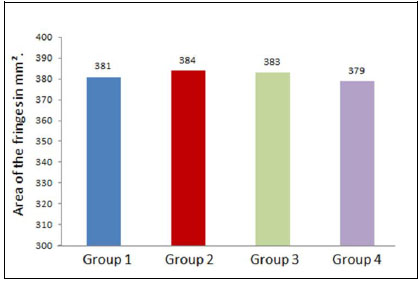
Considering the total area of stress distributed to the surrounding tissues, comparing the two implant lengths, short and standard length implants (both cylindrical and conical) demonstrated a similar load distribution, with comparable mean values, as shown in Fig. (4). No statistically significant differences were found (p=0.82).
With regard to the comparative evaluation of different reference points, in the crestal region, the cylindrical implants (groups 1 and 3) showed a higher stress concentration (p<0.05) when compared to the conical implants (groups 2 and 4); however, in groups 2 and 4, the distribution was more uniform in the three reference points of the evaluation when compared to the other two groups. In groups 3 and 4, the stress distribution followed a very similar distribution pattern in terms of distance and area.
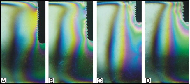
A comparison of the distribution of the fringes revealed an increased stress concentration in the crest region and apical portion of the long cylindrical implant (group 1) and, the conical implants (group 2) showed a more uniform distribution. In the evaluation of distribution of the fringes between short implants, we also observed a more uniform and even distribution of stress in conical implants (group 4), and in the cylindrical implants (group 3), the fringes exhibited a higher concentration (lower distance among different lines) and were less organized and slightly concentrated in the cervical region (Figs. 5 and 6).
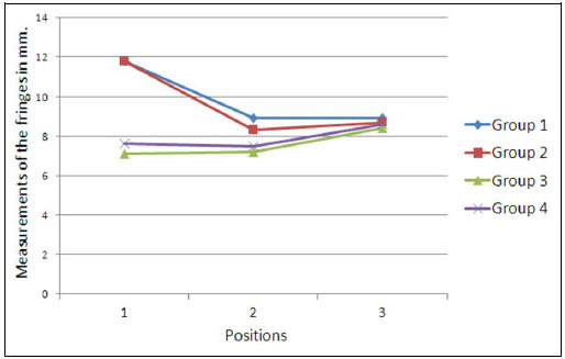
No significant differences could be evaluated between group 1 and group 2 and between group 3 and group 4. However, comparing data from groups of long implants (groups 1 and 2) with the data of groups of short implants (groups 3 and 4), significant differences (p<0.05) were found in values for position p1, which corresponded to the bony crest.
DISCUSSION
The present study reported the results of a photoelastic investigation on stress distribution under laboratory conditions around short (7 mm) and standard length (13 mm) dental implant with a cylindrical and conical design.
In order to adequately interpret the results, some limitations should be considered. Photoelastic investigation is a viable method for studies about stress distribution under laboratory conditions. However, if compared to finite element computerized simulations, photoelastic analysis is more prone to biases in the reproducibility of the experimental conditions. Another limitation of the photoelastic models is related to the methods in taking standardized photographs that were used for data analysis. In this particular study many photographs were taken before obtaining images that could be comparable among them for different groups. With regard to the experimental model, the choice of not performing the analysis under oblique forces could have limited the external validity of the results. In the present investigation, the inclusion of implants in resin was repeated until the image of the stress distribution is symmetrical on both sides. Next, the particular shape of the implants used could limit the external validity of the outcomes of the investigation. Finally, although photoelastic investigations enabled adequate simulation conditions, the particular characteristics of the bone did not allow the consideration of the results of the present study to be completely transferrable to clinical conditions.
Bone stress is one of the major factors that influences bone resorption around dental implants [21-23] The mechanisms of this effect are due to the response of bone osteoclasts, which are activated by excessive physical stress, and induce the disruption of bone tissue in order to minimize the forces [24, 25].
In in vivo clinical setting, the involvement of several factors that affect the stress transmission dynamics to bone surrounding dental implants was evaluated in a number of studies [26-31].
Bone characteristics, in terms of the thickness and density of cortical and medullar bone, have been described to affect most of the patterns and entity of stress distribution [26-30]. A great amount of stress transmitted to bone has been attributable to a decrease in cortical bone thickness [31]. A previous study [28], compared bone quality (D1, D2, D3, and D4 according to the Lekholm and Zarb [32] classification) and stress transmitted to bone tissue using finite element analysis. The authors concluded that more dense bone (D1 and D2) transmitted less force than less dense bone (D3 and D4). In the present paper the simulated bone has one particular density, without any difference between the cortical and the medullar portion. Other factors affecting the dynamics of stress transmission to implant-surrounding bone were related to implant geometrical characteristics, as described earlier [33-37]. Taking into consideration short implants, one study [16], shown that most of the stress transmitted to bone was due to the occlusal load itself and the crown-to-implant ratio affects only a small portion of the total stress. Further, Chang et al. [17] suggested that an adequate occlusal load may contribute to a more proper distribution of stress when using short dental implants. The present investigation showed that the total area of stress distribution to bone was scarcely influenced by the geometrical characteristics of the implants. This is quite obvious because the implant-abutment structure did not show any significant permanent deformation, which can cause a reduction in total load. Moreover, in our study, conical and cylindrical implants did not show any significant difference in area and distance of the stress transmission to bone. This assumption is partially in contrast with the results obtained in a previous study [38], which compared stress distribution around conical and cylindrical implants. However, it should be taken into consideration that the main differences between the two geometrical shapes could have been caused by the size and distance of implant threads, which are completely different from the implants used in the present study. In fact, the outcomes of this study were obtained using implants with a different shape and size of threads and this affected most of the occlusal force transmission to implant-surrounding bone [39, 40]. However, comparing the fringe distribution, the images showed an increased stress concentration in the crest region and apical portion of the long cylindrical implant (Group 1), and the implant conical (Group 2), demonstrated a more uniform distribution. Taken together, these data were consistent with the aforementioned study [38]. In the fringes of short implants, it was also possible to observe a more uniform and even distribution of stress in the conical implants (group 4). For the cylindrical implants (group 3), the fringes had a higher concentration and were less organized and slightly concentrated in the cervical region.
CONCLUSION
The present study showed that the implant length seemed not to affect the total amount of stress distributed to the implant-surrounding bone under axial loading condition. Higher stress concentrations (calculated measuring the difference between fringes) were transmitted by longer implants than shorter ones, independent of implant shape. However, the short implants had a lower concentration of stress on the crestal bone region when compared with long implants. Thus, further investigations may help to provide a deeper understanding of the effect of implant length on stress distribution.
CONFLICT OF INTEREST
The authors confirm that this article content has no conflict of interest.
ACKNOWLEDGEMENTS
Declared none.

